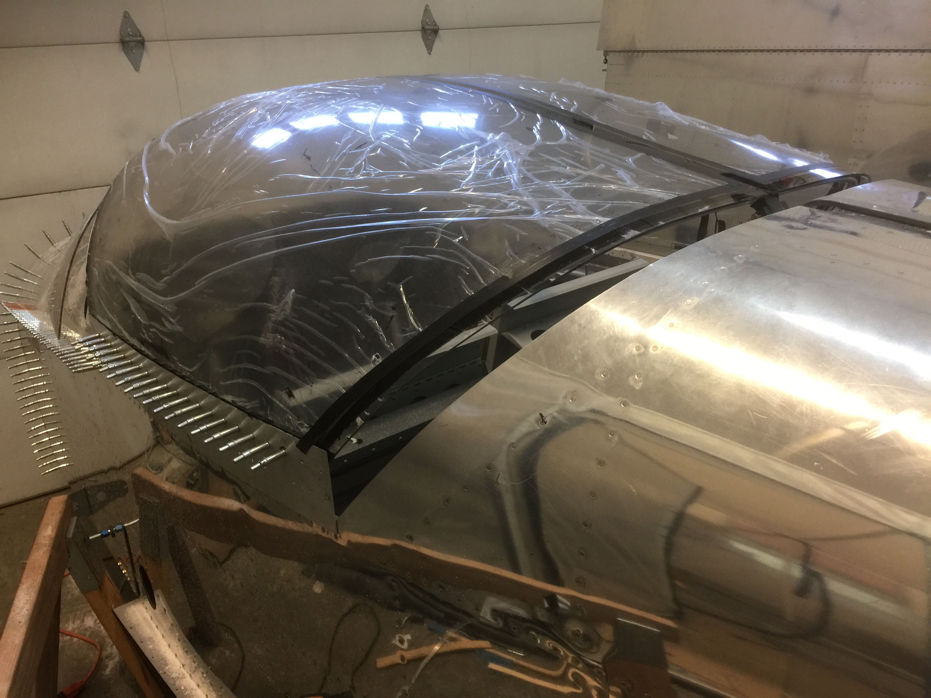
Drilled and installed screws to canopy rails.
Time: 4 hours.
Drilled and installed screws to canopy rails.
Time: 4 hours.
Installed aft canopy skirts.
Time: 8 hours.
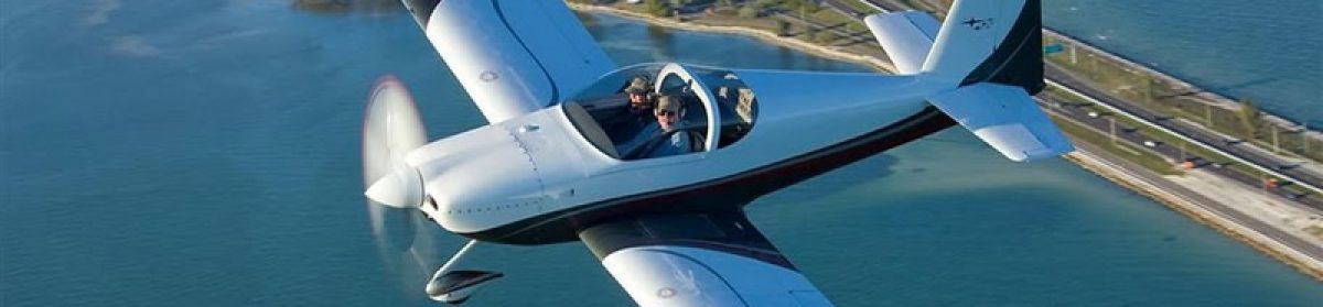
Sikaflexed the canopy.
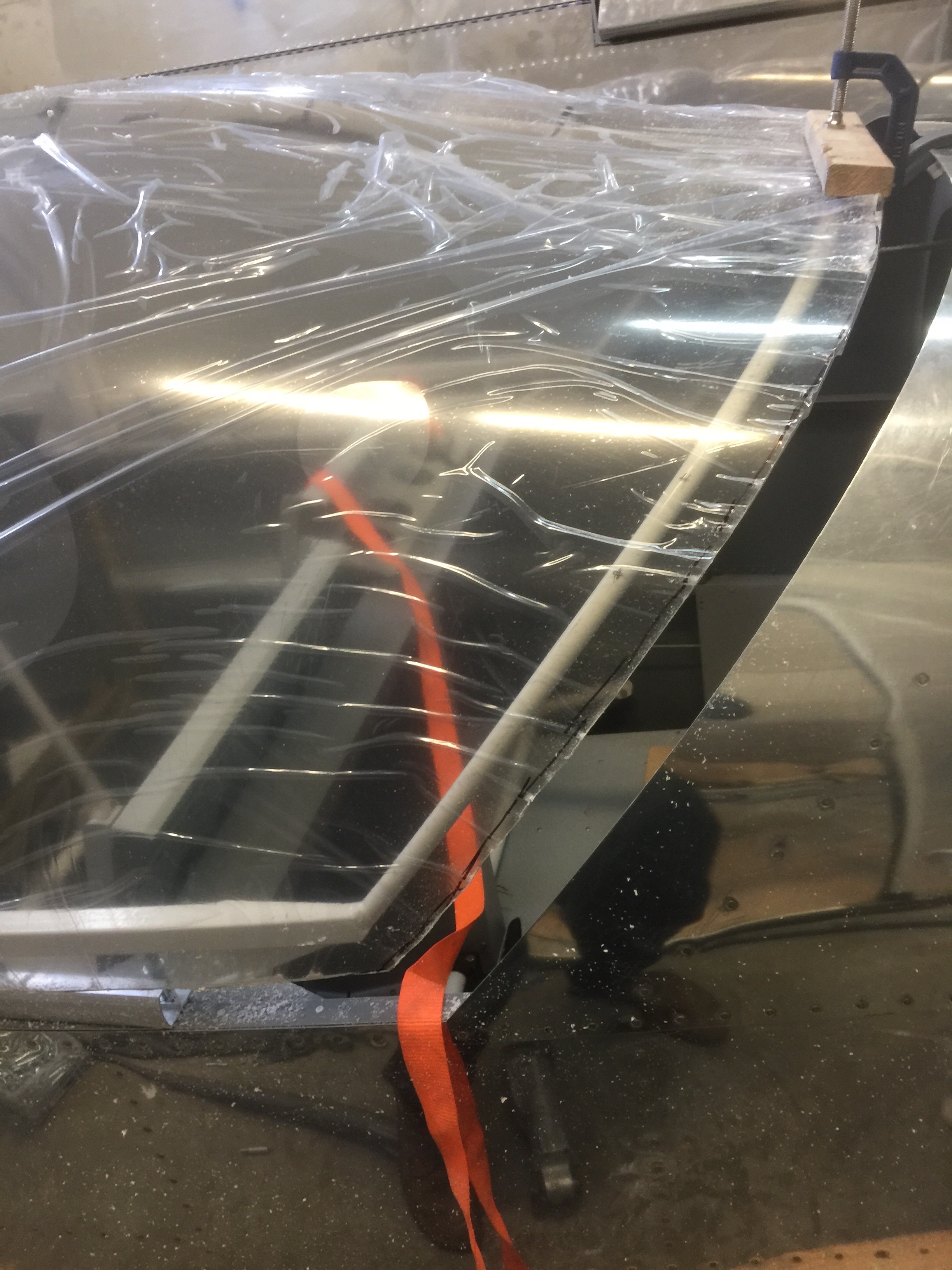
Time: 6 hours.
I checked the shape of the C-763 Slide Spacer against the full-scale template on DWG 41 as the part supplied in my kit varied slightly, so I carefully adjusted C-763 to match the template.
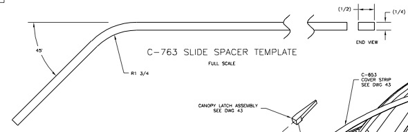
I completed the rear slider track assembly by positioning, drilling, and riveting the C-762 and C-763 parts together per DWG 43, Section H-H.
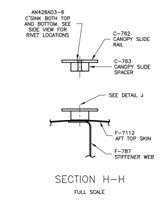
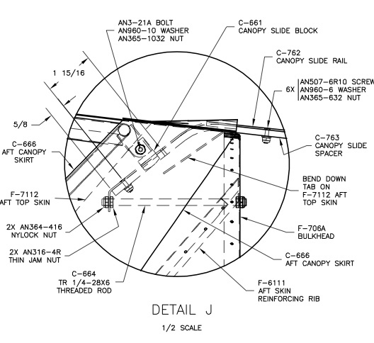
Make sure that you are not changing the shape of C-763 as you are attaching C-762 to it. Lay the track assembly in place approximately centered on the rear fuselage top skin. Bend the tab in the F-7112 skin down to allow the track assembly to rest on the skin. See DWG 43, Detail J.
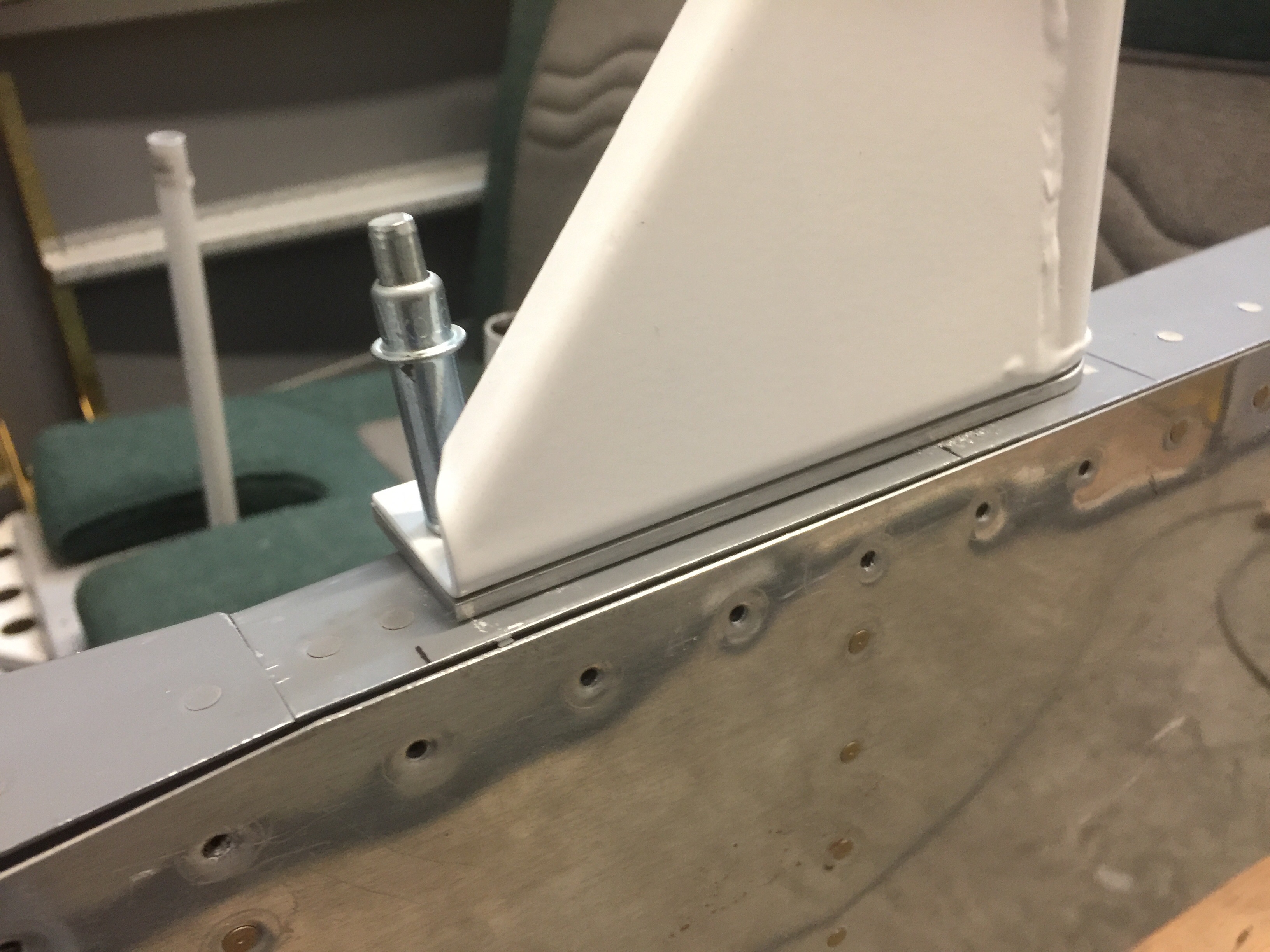
I then slid the C-661 block onto the track and held it in place on the fuselage with duct tape.
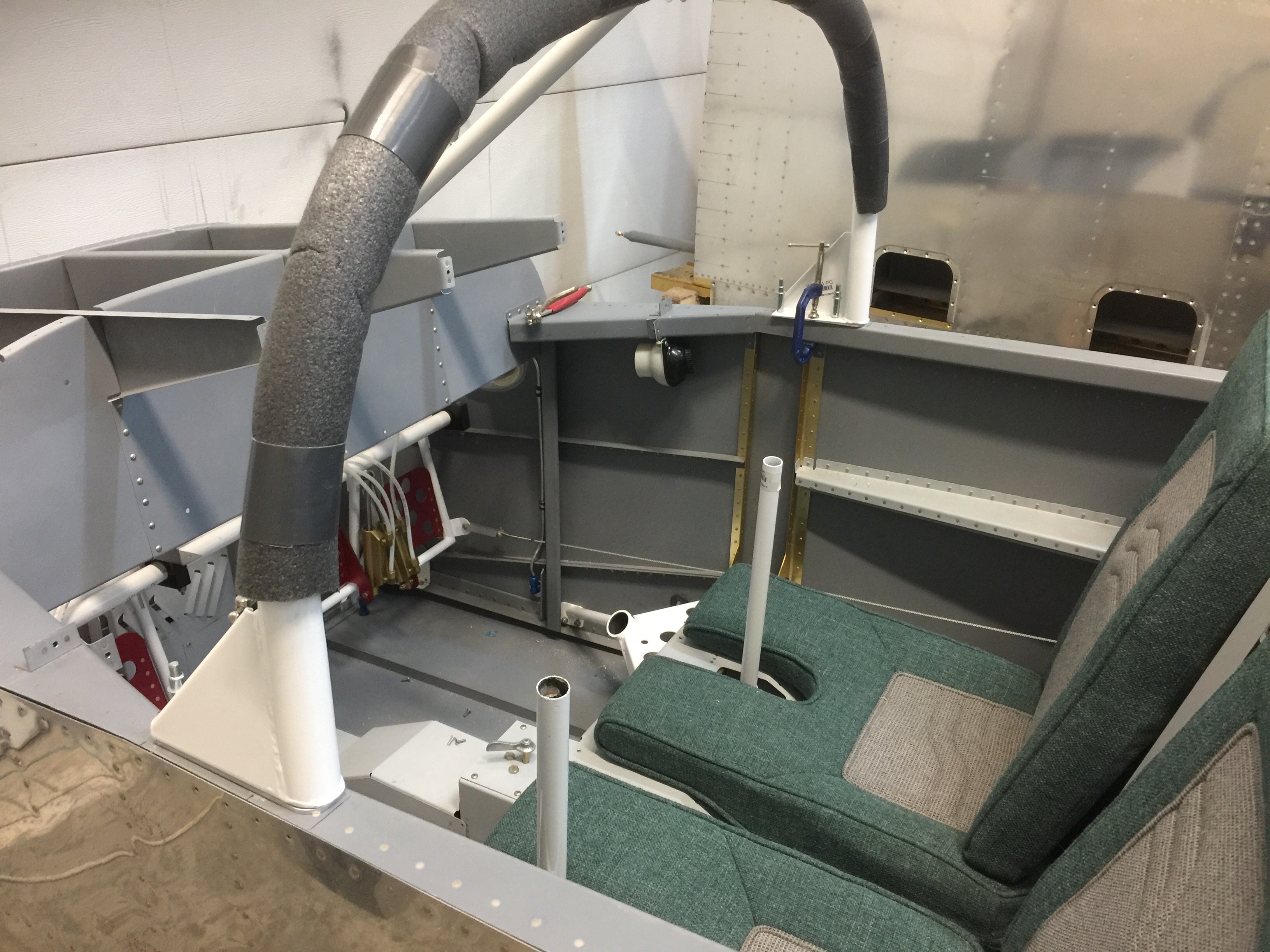
I installed the Wd-640 Canopy frame on the fuselage by inserting the rollers in the tracks through their open aft ends and inserting the bolt through the C-661. I slid the frame forward until it met the roll bar. The flanges of the Wd644 roller brackets were to be the first part of the frame assembly to touch the roll bar.
Time: 8 hours.
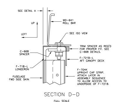
I laid out and drilled #40 pilot holes for the 3/16” and ¼” bolts through the F-721B Aft Canopy Decks as shown on DWG 42, Detail A. I then drilled the aft pilot hole through both the upper surface of F-721B and the lower flange of F-721B.
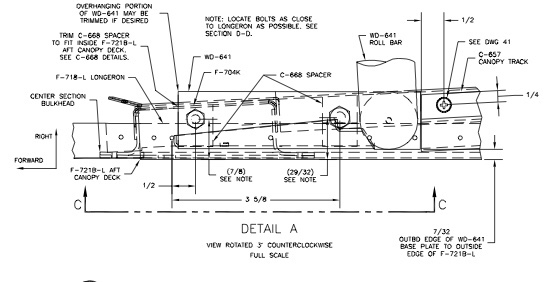
The C-668 spacers were needed to provide a flat surface for the nuts and bolts that attach the roll bar to the longerons. See DWG 42, Section D-D.
I modified the C-668 spacers provided in the kit as shown on DWG 42, C-668 Detail Views.
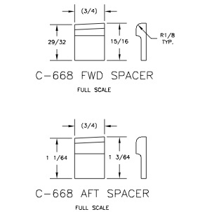
When done, I had a forward left, forward right, aft left, and aft right spacer. The centerlines were marked on the upper surface of each spacer. I held the spacers, one at a time, in place against the bottom surface of F-721B and nested them tightly against the inboard edge of the longeron with the fastener centerline mark visible through the #40 pilot holes I drilled earlier. I drilled #40 through the pilot holes just enough (about 3/32” deep) to make a good center point for finish drilling the holes through the spacers off of the fuselage. I then removed the spacers and used a drill press to drill the #40 holes all the way through the spacers. Then I finish-drilled the holes to final size. I was careful to put the correct size hole in the correct spacer! #12 for the forward two spacers, ¼” for the aft two spacers.
I placed the Wd-641 Roll Bar on the fuselage in the position shown on DWG 42, View C-C.
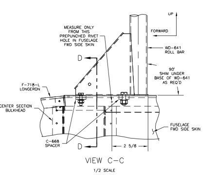
The roll bar needed to have a 7/32” gap between the fuselage sides and the outer edges of the bar. If the gap had been within 1/16” of desired, I could have pushed or pulled it into position, otherwise I would have had to bend it slightly to make it fit within 1/16”. It could be adjusted quite easily by hooking one end behind something and pulling (to make it wider) or by putting one end on the floor and leaning on the other (to make it narrower). I went very slowly, as it was easy to do too much.
Once I had the width close, I clamped the roll bar in the proper position of the fuselage (vise grips worked well) and using a #40 bit, I back-drilled the 4 bolt holes up from the bottom using the pre-drilled pilot holes in F-721B as guides. The aft two holes were back-drilled using the holes in the F-721B flanges as well as the holes through the upper surfaces.
Time: 8 hours.
After the empennage, the sliding canopy probably raises more questions than any other installation. Fitting a structure of welded steel spaghetti to a hand-built fuselage is an exercise in patience and perseverance. Given the inevitable variations between individual frames, roll-bars and fuselages, it is not possible to give dimensions that will work every time. Instead, builders are cautioned to slow down and work carefully from “first principles.” The amount of effort and time spent on preliminary positioning and alignment, adjusting both the canopy frame and the canopy skirts, makes a big difference to the quality of the final fit of the canopy.
The RV-6/6A Sliding Canopy Assembly consists of two main components; the Windscreen/roll bar assembly which is fixed to the fuselage, and the Sliding Canopy Frame/Plexiglass canopy which moves fore and aft.
The windshield frame also serves as an overturn structure or “roll bar”. It consists of a formed steel tube weldment with a flanged base which is bolted to the fuselage upper longerons and cockpit rails. The roll bar also includes a center brace which attaches to the upper forward fuselage. The windscreen is screwed to the roll bar and bonded to the top fuselage skin with an epoxy/fiberglass base molding.
The sliding canopy frame of is made of welded steel tubing and moves on nylon rollers and slide blocks. The canopy is trimmed and attached to the steel tube frame with blind rivets and machine screws. Aluminum skirts are used to fair the bottom and rear of the canopy to the fuselage.
The canopy has three contact points with the fuselage; two rollers at the lower forward corners of the canopy frame, and one slider block at the rear top of the canopy frame. The rollers move in extruded aluminum tracks and the rear slider block moves on a builder-fabricated guide track.
The sliding canopy is held closed with an over-center spring-loaded hook latch operated by an internal/external handle. This handle is also used for sliding the canopy open or closed. There are two pins at the rear base of the canopy just aft of the canopy tracks which engage nylon blocks mounted on the fuselage. The front of the sliding canopy is held down by a molded fiberglass lip on the windscreen. The pins and lip serve as passive hold-downs, so operating the sliding canopy requires just one latch and one hand.
Time: 3 hours.
