Setting the Wing Incidence – 5

I installed the WD-610 control column, WD-611/WD-612 control sticks, and F-665 control column pushrod as shown on DWG 38. I used the W-730 bellcrank jig to hold the WD-421 bellcrank in its neutral position as shown on DWG 15A. I installed and adjusted the W-818 aileron-to-bellcrank pushrod such that the aileron was in the neutral position when the bellcrank was held in its neutral position. I installed and adjusted the W-716 bellcrank-to-stick pushrod such that the sticks were in their neutral positions (vertical) when the bellcrank was held in its neutral position.

DWG 38
DWG 15A

Time: 4 hours.

Setting the Wing Incidence – 3

I assembled the F-759 flap pushrods as shown on DWG 33.

DWG 33

I bolted the F-759 to both the flaps and the Wd-605EF flap control weldment. I borrowed a battery from my lawn tractor and connected it to the flap motor. I ran the motor up and down while checking for any possible interference in the flap linkage. The hole in the fuselage skin was enlarged to avoid interference with the pushrod.

Time: 4 hours.

Setting the Wing Incidence – 2

After the F-796A was bolted, temporarily, to the fuselage, the clamp could be removed. I located the center of the 1/4” hole on the flange of the angle, double checking to be sure that there was sufficient edge distance on both T-405 and F-796A. I drilled the 1/4” hole through T-405.

I finished the bracket installation after the wings were removed by installing the nutplate on T-405 as shown in DWG 38 Detail F and Section E-E. I noted the orientation of the platenut as it was important.

Detail F
Section E-E

Time: 8 hours.

Setting the Wing Incidence

With the main spar bolted in place, the next step was the attachment of the rear spars. I leveled the fuselage, both laterally and longitudinally, using the top surface of the F-718 longerons between F-704 and F-705 as a datum surface. I then squared the wing with the fuselage. This was done by measuring from corresponding points on the wing tips to a common centerline point of the aft fuselage.

I equated these distances at the same time checking that the wings had no forward or aft sweep. This was done by dropping 4 plumb lines from the wing leading edges (2 on each wing at inboard and outboard points) to see that they all fell in a straight line. I marked this position with a vertical line at the rear spar attach, on both rear spar and center section.

Checking Sweep

Now the very important incidence angle had to be measured and set. This was done by using a level and spacer blocks as shown in DWG 38. I verified that the fuselage was level and rested one end of a level on the forward spar just forward of the skin butt joint and the other end on a spacer placed directly over the rear spar web. I shifted the rear of the wing up or down to center the level. The spacer size was calculated to provide the desired 1 degree positive incidence angle. I checked several points along the span of the wing to verify the reading. I clamped the root in place and checked the other side in the same manner. See DWG 38, Section H-H.

Incidence Angle

It is extremely important to verify that there was at least 5/8” from fastener center to the edge of the part, in both the rear spar and F-705.

I initially drilled an undersize hole starting with a 1/4” drill. Then I progressively enlarged the hole to 5/16” to provide a close fit for an AN5 bolt. Drilling with a long stiff drill bit was a good idea because it could be held straighter for a truer hole.

Drilling the Rear Spar

The overlapping portions of the F-776 bottom skin were to be screwed to the bottom of the wing when the wings would be installed to stay. Holes for these screws had be drilled now. I used the reference lines to locate the hole positions. After the wing was removed, these holes were dimpled for #8 screws. K1100-08 platenuts were riveted to the inside flange of the root rib.

The F-796A Fuel Tank Attach Brackets were fitted to the fuselage as shown on DWG 38, Detail F. The bracket needed to have the main web adjusted by bending so that it mates flush to the fuselage side and to the T-405 angle bracket on the fuel tank, as shown on DWG 38, Section E-E. I clamped the F-796A angle firmly to the T-405 bracket on the fuel tank. I checked to see that it rested firmly against the fuselage and then drilled the attach holes.

Time: 6 hours.

Wing/Fuselage Assembly

During this phase of construction it was necessary to assemble the wings to the fuselage for a number of reasons including drilling the rear spar/center section attach, finishing the aileron and flap control mechanisms, installing the wing tank/fuselage attach brackets, fabricating and fitting fuel & vent lines, and installation of wing root fairings.

Before installing the wing, I marked on the W-704 the screw locations at each unused rivet space on the bottom flange of the W-710 root rib. I then marked a straight line from the hole location toward the wing tip and made a measured mark 3” outboard from the intended screw location. This allowed me to measure back to the same point on the overlapping F-776 fuselage skin.

Since my shop dimensions were such that the aileron pushrods could not be inserted from the tips of the wings, the W-716 pushrods had to be loosely placed in the wing lightening holes from the root before the wing panels were “plugged-in” to the fuselage.

Wings mounted

Actual installation of the wing panels turned out to be very simple, as the spars had been fitted and drilled at the factory. It was helpful to file a slight bevel on the root ends of the spar to assist getting it started sliding through the slot in the fuselage bulkhead, and to prevent it from scratching and galling the bulkhead bars as it slid through. I supported the inboard ends of the wings when inserting to prevent the bottom of the spar from dragging along the inside of the fuselage bottom skin. As the wings were pushed in near center, I made sure that the fuselage center bottom skin (which overhangs the fuselage) didn’t catch on the wing skin. When bringing the spar into its exact position, lining up the bolt holes in the bulkhead and spar, it was helpful to use drift pins. These were made from hardware store bolts with the ends rounded and tapered on a grinder. Gently driving this lubricated pin into a nearly aligned hole centered the bulkhead/spar hole so that the bolts could be installed without excessive force. I followed the recommendation that 7/16” and ¼” hardware store bolts be used for test fitting to prevent damage to the holes and NAS bolts. I installed the bolts as called-out on DWG 11. For fitting purposes, it was only necessary to install four 7/16” bolts, one top and one bottom for each wing panel. Of course, when permanently installing the wings all the bolts called-out on DWG 11 must be installed.

NOTE: When installing the wing for the last time, I will lubricate the NAS bolts with LPS #2 (available in a spray can). I will not lubricate the threaded portion of the bolt as this would influence the torque wrench reading.

Time: 4 hours.

Installing the Landing Gear Mounts

Thee main landing gear mount installation is shown on DWG 34A.

Before fitting and bolting the mount to the fuselage, the upper gear leg alignment bolt hole had to be completed. I made sure that the inside of the mount tube and the knob on upper end of the gear leg were clean and had no burrs around the holes.

I then slid the gear leg into the mount and aligned the hole.

I match drilled the leg to the mount using a 0.311” drill bit.

I removed the leg and cleaned up the burrs.

I installed the WD-721 landing gear supports to the forward side of F-704. I needed to slightly enlarge the elliptical openings for the landing gear weldments to pass through the floor as well as the flange of the main spar. I also needed to slightly adjust the angle of the WD-721 flange that mates up to the vertical leg of the lower longeron at its aft end. I also checked the fit of the forward pointing brace tube of the WD-721 weldment.

I had to open holes in the WD-721 that didn’t line up with the main spar holes. I did not drill through the spar, but marked the holes, removed the weldment and used a round file to remove just the area of interference.

I was careful to not forget the additional washer between the mount and the lower part of the spar as called out on the plans.

As there was a gap of less than 1/16” it was acceptable to pull it tight to the longeron with the bolts. If it had been more than 1/16”, I would have had to use a spacer made from aluminum scrap or rebend the brace tube slightly as required.

I drilled 3/16” diameter holes through F-770 and F-7101, 7 places per side using pre-punched holes in WD 721 as drill guides.

Time: 4 hours.

The Electric Flaps

Electric flap actuation is standard on the RV-7/7A. The power comes from a sealed motor/gear drive assembly between the seat backs, driving the flaps through a welded steel actuator and pushrods connected to the inboard end of the flaps. The flap mechanism is shown on DWG 33.

I began by drilling the holes in the clevis ends of WD-613-EF flap actuator to ¼”.

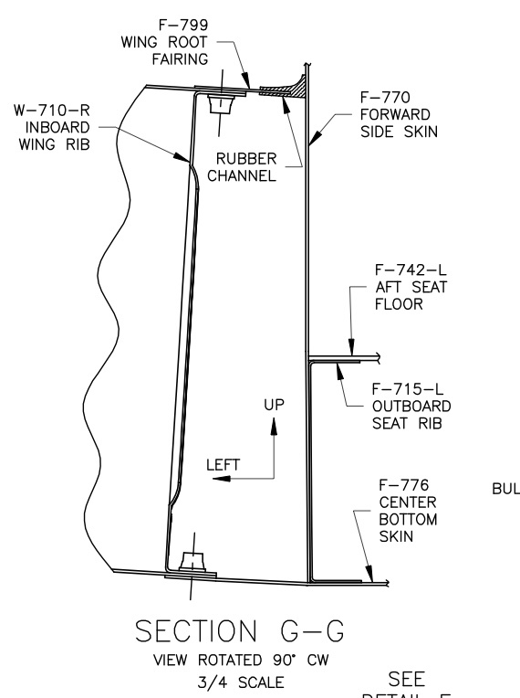
I drilled the holes in the F-680 block and sawed it in half.

I drilled the safety wire hole shown in Detail E and installed the rod end bearing and jam nut on the end of the ES-85615-157 flap motor shaft.

I installed the flap actuator in the baggage compartment using bearing blocks F-661-EF on the F-705 uprights and F680 in the center. The forward corner of the F-748 cover had to be notched to clear the F-680 block, so it can be removed without removing the block. I used the holes in the F-680 block as a template to drill the floor.

I made the F-766C plate, but drilled only the indicated index hole in it at this time.

I made the F-766B angle, the F-785B attach angle, the F-766D Spacer and F-767 Attach Plate. I pre-drilled the angles, but didn’t drill the attach plate.

I fit and riveted the F-758 bracket to the bottom end of the F-766A channel and installed the nutplates along the sides.

I centerlined the F-766C plate and match drilled it to the F-766A channel. I riveted the pieces together and drilled the bolt hole full size.

I fit and riveted the F-785B attach angle to the bottom of the F-785A backrest brace.

I temporarily screwed the F-758/766A assembly to the floor and clamped the F-767 attach plate to the top of the channel. I clamped the attach plate to the crosspiece of the F-705 bulkhead and adjusted it until it aligned with the pre-punched holes in the bulkhead. I drilled the F-767 to both the F-766A and the bulkhead.

I removed the channel and finished F-767 by fitting the nutplates and riveting them to the top of F-766A.

I installed the F-766 assembly in the fuselage.

Then I slid a bolt through the F-766B angle, the flap motor, the washer and the F-766D spacer referring to Section B-B’. I used a 12v battery to run the motor until the shaft was half way between its travel stops. Reversing the leads to the terminals made the motor run the other way.

When the shaft had stopped at half travel, I bolted the motor to the Wd-613-EF actuator arm, using the washers shown to center it in the clevis and installed safety wire as shown in Detail E. I rotated the arm and bracket until it rested against the inside of the F-766A channel and bolted the assembly to the channel. I then clamped the F-766B bracket to the channel and drilled it, using the holes in the channel as guides.

I removed the bracket from the motor and riveted it to the channel. I re-installed the motor, using the spacer, etc. on top as shown in Section A-A’ and was careful not to forget the cotter pin.

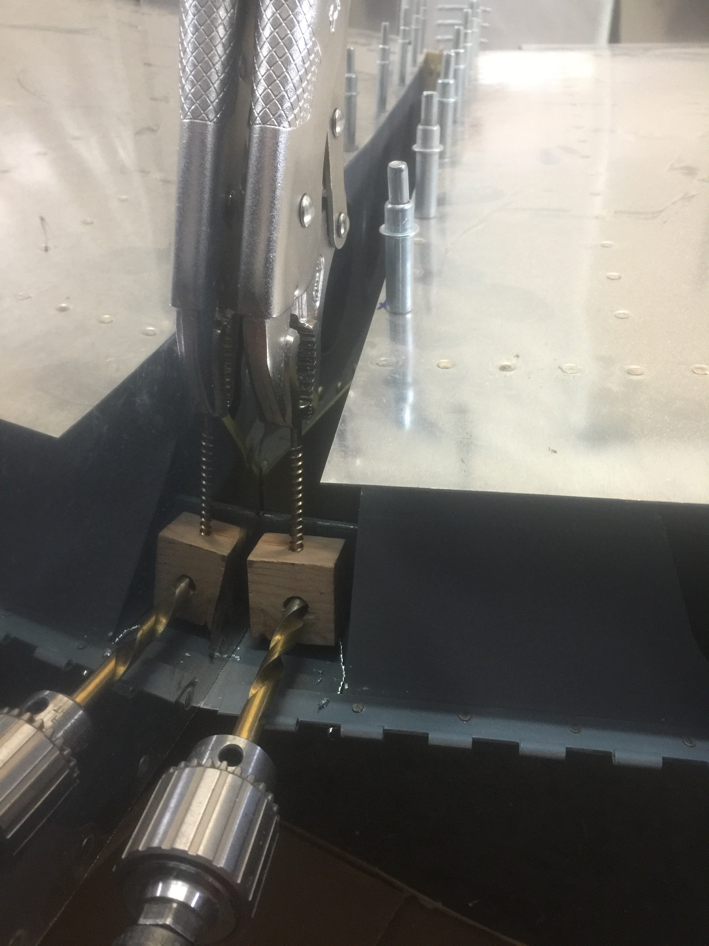
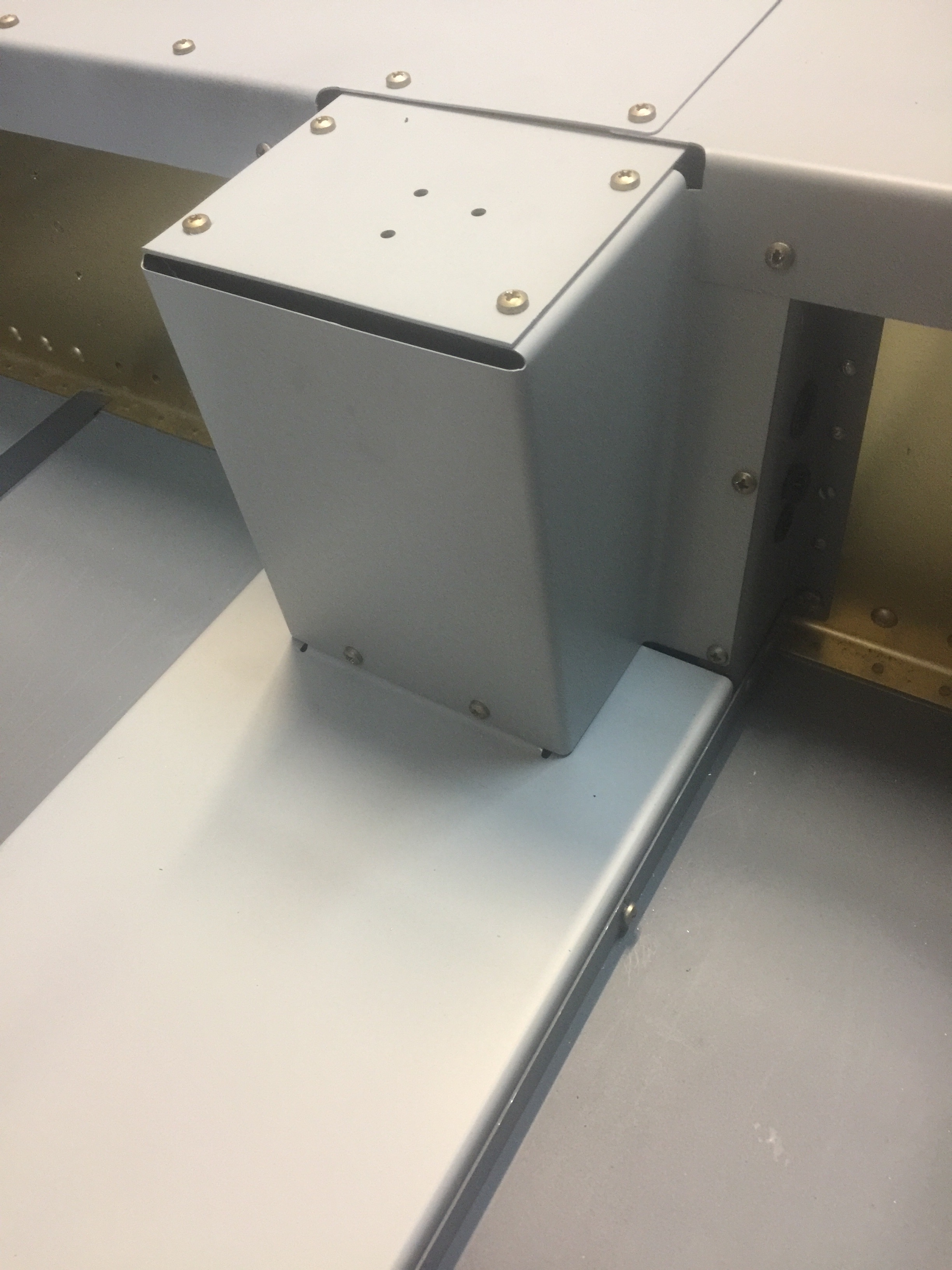
I installed the F-785A backrest brace and began fitting the F-760 Flap Actuator Covers. I matched the holes with nutplates in the F-766 channel, clecoed, and drilled the rear row of holes. I was able to enlarge the hole around the bolt head with a unibit. I drilled the backrest, using the side cover as a guide. I removed the backrest, installed the nutplates and re-installed it in the fuselage.

The final details of wiring and adjusting the F-759 pushrods were left until the wings and fuselage were joined.

Time: 14 hours.

Forward Covers

Several covers are installed in the forward fuselage to protect fuel lines, cover the electric fuel boost pump and direct cabin heat. These are removable for maintenance.

I fit the F-982E Access Plate and F-982D Heat Baffle to the F-782C Center Cabin Cover. I then riveted the baffle the necessary nut plates to F-782C.

Heat Baffle

I inserted the F-782C between the center floor reinforcement angles and the F-601N vertical angles on the firewall. I checked to make sure an even amount of the horizontal section of F-782C was exposed above the floor angles. I had to be careful not to force it down too far as the flanges would be forced inboard by the radius of the angles and a poor fit would result. I used a simple wood spacer between the cabin floor and the center cabin cover to ensure that this wouldn’t happen.

I riveted the nutplates to the F-983A Fuel Valve Plate and screwed it to the F-704 bulkhead. I the slid the F-983C Fuel Valve Cover underneath the plate and fastened it to the F-783B cover support ribs and the fuel valve plate.

Fuel Valve Cover

I adjusted the F-782C fore/aft until it mated with the bottom of the F-983C, Fuel Valve Cover and clecoed the two parts together.

I fit the forward section of the F-782C to the firewall and F-601K-1 firewall recess. I rechecked the height of the F-782C and drilled it to the floor stiffener angles and finished drilling it to the firewall as well.

I removed the fuel valve cover and center cabin cover components and installed the necessary nutplates. As I am installing electric elevator trim, the triangular flange on top of the F-983A could be trimmed away.

Time: 12 hours.

Seat Backs

I re-installed the floors with enough screws to hold them securely and then proceeded to make the seat backs as shown on DWG 30.

The upright angle supports are made from 0.125 angle material (not 0.063!). The seat backs were very simple, but once the hinges were mounted on the bottom, they became “right” and “left.” I was careful to make one of each.

Seat Backs

The F-638 Seat Back Braces were trimmed on the ends and the optional lightening holes were cut on the drill press with a fly cutter.

Time: 8 hours.