Assembling the F-706 Bulkhead and Bellcrank Support Ribs

The F-706 ring bulkhead is made of three pieces.  The F-729 bellcrank rib, F-728 Bellcrank Channel, F-730 Plate and F-729C Angle all attach to the aft side of the F-706B Bulkhead Bottom.

I used a unibit to enlarge the rudder cable holes on all these bulkheads.

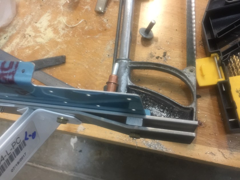
I made the F-729C angle.

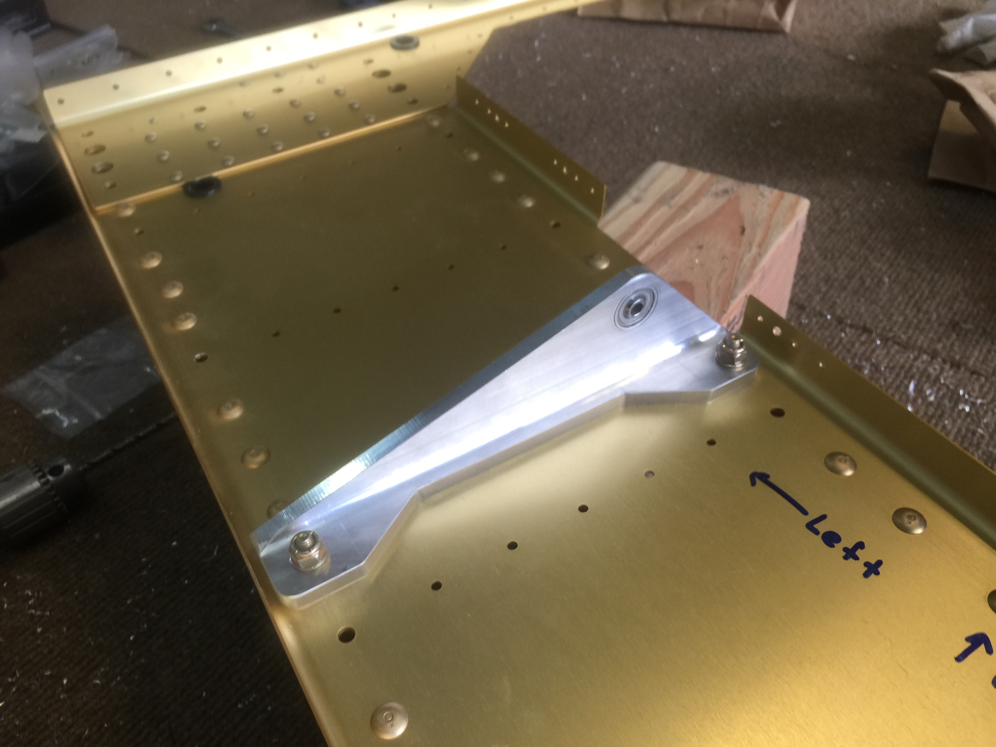
I then drilled and riveted the F-729A bellcrank rib and F-729B angle together.  I was careful to drill the 1/4″ hole for the bellcrank pivot bolt.

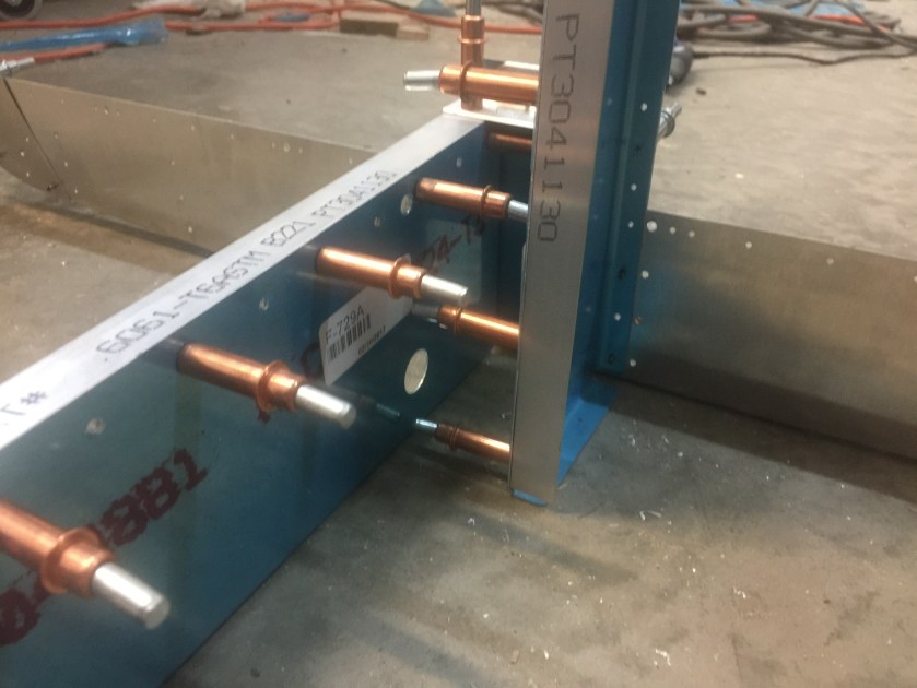
I drilled the F-728A Bellcrank Channel to the F-728B angle, but did not rivet them together yet.

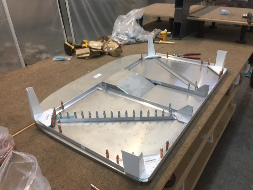
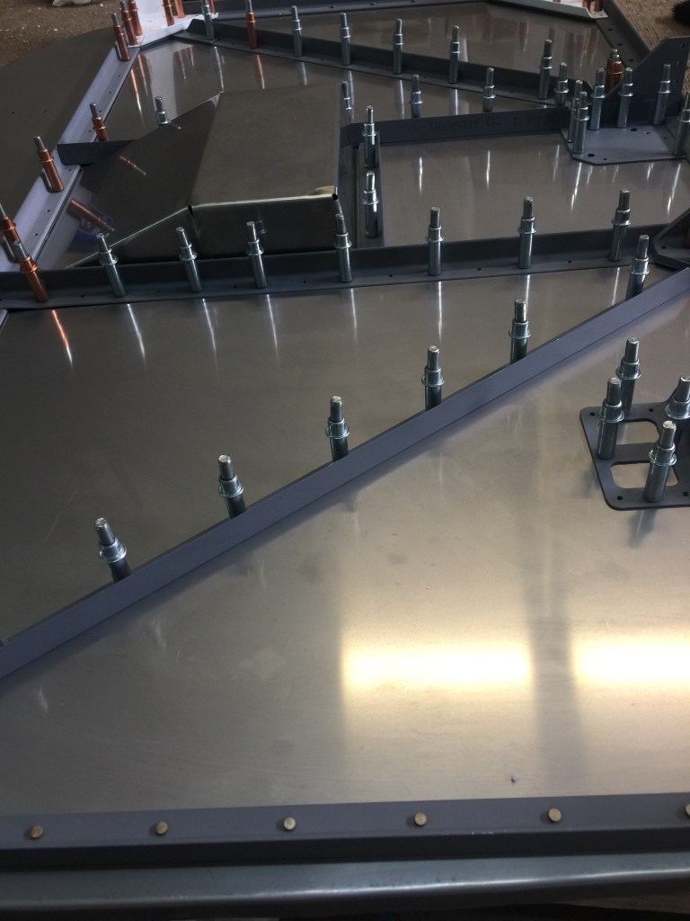
I began assembly of the bulkhead by drilling the F-730 plate, F-728, F-729C and F-729 rib to the F-706B Bulkhead Bottom. After deburring, I riveted the assembly together, except for the F-728 channel. I left that clecoed for now.

D9C42BB2-8435-48D5-A3F7-10218E0AE5F80FD19F38-3AB0-4069-92DE-66A84AE43E3E27AC2335-345B-4491-BFF8-F270CE108A78

Time:  4 hours

Assembling the F-705 Bulkhead – 3

I fitted and drilled the F-661EF flap actuator bearing blocks.  I drilled out the bearing blocks with a #10 drill in order to fit the bolts. Once the blocks were fitted, I removed and stored them as they would interfere with skin riveting.  They will be bolted on permanently when the flaps are installed.

I bolt the seat belt anchors and F-705H spacer to the lower bulkhead.

img_7203

img_7200

Time: 2 hours

Assembling the F-705 Bulkhead – 2

I drilled and riveted the F-705J Angle, the F-705K Plate and the F-705-L seat adjustment supports to the F-705F Channel.

I then drilled the snap bushing holes and installed the nutplates on F-705D.

Then I clecoed the F-705A, D and F bulkhead components together.  Before riveting the F-705 bulkhead assembly together, I studied the NOTES on DWG 20 to know which of the various holes needed to be left open so that other pieces could be attached later.  I covered these holes with tape.  I also noted the holes that needed to have flush rivets installed and machine countersunk them.  Then I riveted the F-705 bulkhead together.


Time: 4 hours

Assembling the F-705 Bulkhead

The F-705 bulkhead supports the seat backs, strengthens the open cockpit and provides the attachment for the rear wing spar. I first marked a lengthwise centerline on the rear face of the F-705B center section bar. I then located and clamped the F-705B, the F-605C Bar Doublers and the F-705H Spacers to the F-705A Rear Spar Attach Bulkhead. I drilled the assembly using the prepunched holes in the F-705A as a guide.

Then I drilled the F-634 seat belt anchors to the F-705 lower bulkhead assembly. One of each pair of anchors was drilled first. It was then bolted to the F-705A, then a 3/16″ shim was put between it and the other anchor and the three pieces were clamped together. The flange of the unbolted anchor was then clamped to the bulkhead. Drill the anchor using the prepunched hole in the bulkhead as a guide.

In some cases, the flange of the seat belt anchor would come close to an adjoining rivet or bolt hole. So I had to grind or file the flange of the seat belt anchor to allow for bolt or rivet heads as necessary. I was careful to preserve a 2 diameter edge allowance from the center of the anchor bolt hole to the edge of the anchor flange.

Finally I disassembled and prepared the F-705A lower bulkhead for riveting and drilled the snap bushing holes to full size.

Time: 6 hours

Assembling the F-704 Bulkhead – 2

I then prepared the F-782B-L&R and F-783B-L&R Cover Support Ribs. I drilled them to the bulkhead, then removed them and installed the nutplates.  I drilled the snap bushing holes to full size.  I then fabricated the F-704M Web Stiffeners and drilled them to the F-704A.  I then riveted the Cover Support Ribs and Web Stiffeners to F-704A.  I made the F-904J Center Section Spacers from the rigid aluminum tube provided.  I squared up the ends by chucking them in a drill press and spinning them gently against a piece of sandpaper held flat on the drill press table. I made spacer blocks from thick plywood to hold the halves of the center bulkhead assemblies exactly 1.438” (1 7/16”) apart to match the thickness of the spar. I then drilled the blocks with oversize holes to allow the bolts to run through the spacers. I bolted the two center bulkhead assemblies together around the spacers for a trial fit. I did not rivet the F-704H side plates on now as they will be riveted to the center section after being riveted to the side skins to allow some potentially difficult rivets to be set easily. After I was sure that everything fit correctly, I removed the bolts and spacers so the bulkhead was once again two separate halves, fore and aft and stored all the bolts and spacers in a bag and taped the bag to the bulkhead.

img_7131

Time: 2 hours

Assembling the F-704 Bulkhead

I started working on this massive assembly by drilling the holes that will receive snap bushings to full size.

I then attached the F-704C-L&R Center Sections to the F-704A forward bulkhead and the F-704D-L&R Center Sections to the F-704B aft bulkhead. I assembled the components with clecos and put a NAS1307 close tolerance bolt through one hole on both top and bottom to align the parts exactly. On the aft F-704B, l located the F-704G shear bars with bolts and clamped them in place. I drilled the rivet holes to final size, and then disassembled, deburred and dimpled the parts. The rivets attaching the F-704G bars were installed with flush heads on the forward side.

I then fabricated the F-633 Control Column Mounts. I drilled the first bolt hole to the dimensions shown, then bolted the F-633 to the aft F-704. I squared it carefully and then back-drilled the second hole through the pre-punched hole in the bulkhead. After the holes were drilled, I trimmed away the area shown to save weight.

Time: 8 hours.

Assembling the Firewall – 4

The next thing I did was to rivet all the components of the firewall together, except the F-601K-1 recess. Leaving the recess out will allow a good access through the firewall and make installing the rudder pedal brace much easier.

As the firewall keeps fumes and liquids in the engine compartment from entering the cabin and some of the bent corners have unavoidable openings, especially around the firewall recess and the lower corners of the firewall, I will need to seal all openings with fuel tank sealant after skinning the fuselage.

Time: 6 hours.

Assembling the Firewall – 3

I needed to make provision for the brake lines by riveting a F-6122-1 bracket to the firewall. This is the bracket that holds the fittings that connect the flexible brake hoses from the master cylinders to the solid brake lines leading to the wheels. I then drilled the Bracket to the firewall as shown on DWG 19, Firewall Bulkhead Rear View.

Then I clecoed in the firewall recess (necessary to provide room for the oil filter and prop governor) F-601K-1 in the square hole centered in the F-601A-2 bulkhead and drilled all the holes to full size.

Then I fit and drilled and riveted the F-601Z Fuel Pump Doubler to the lower firewall. The nutplates were on the forward side of the firewall and the rivets holding them penetrated both the F-601A-2 stainless firewall and the F-601Z doubler.

Next I disassembled the firewall, dimpled F-601A-2 and F-601K-1, then machine countersunk the underlying stiffeners and spacers. I built the firewall using flush head rivets, with the flush heads on the forward side, giving it a smooth surface and making the firewall easy to clean and easy to fit brackets, etc.

Time:  6 hours.

Assembling the Firewall – 2

I positioned and clecoed the stiffeners, spacers, gussets and weldments to the matching holes in the firewall. I drilled and clecoed the remaining holes, using the firewall as a guide. I then fabricated the F-601P spacers and F-601E stiffener and installed them.  I needed to round some edges of F-601J and the ends of F-601N-L&R to fit the inside radius of the aluminum angle they rested upon.  I squared F-601J-L&R with the F-601N and F-601M stiffeners.  I aligned F-601J-L/R horizontally by nesting their inboard face with the outboard face of F-601N-L/R, using the dimension given on DWG 19 for vertical alignment.  I clamped  F601J-L&R and underlying shims F-601H-1 and F-601G-1 lightly in place and aligned the pre-punched holes. I then tightened the clamps and back-drilled F-601J through the firewall.

Firewall Assembly Work

Time: 3 hours