I began by finding the AA6-125 longeron angles which were shipped in my wing spar box. I then measured and trimmed them to the correct length. I trimmed the horizontal face on the aft end of the angle as shown on Detail C, DWG 18.
I was bending a left and right version of the F-718 longeron. To avoid confusion I marked the angles as left and right longerons and specified the front, rear, top and side.
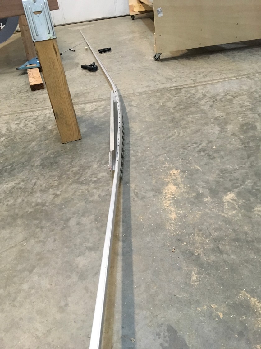
I laid the longerons side-by-side on the floor with the ends matching and marked the starting and ending point of the shallow curve, looking down. This bend follows a line 0.032” inside the outside edge of the F-721B Aft Canopy Deck. I marked the location of the sharp downward bend, in side view. This bend occurs at the front end of the F-721 B.
Bending the Shallow Curve
I bent the F-718 longeron angle in my sturdy vise mounted to my solid, stationary table. I padded the jaws to protect the longerons from gouges and scratches.
I held the angle in the vise, pulled on the free end and established a small “pre-load” on the angle and then gave it a small-to-medium whack with a rubber hammer to produce the bend. I made several small, progressive bends to form the curve.
I cut the template from DWG 17 and glued it to a piece of stiff cardboard. This served as my guide while bending the longeron. I made both sides useable so it would work on both the left and right longeron.
I clamped the angle in the vise so the end of the jaw was one inch aft of the aft mark. I started bending at the mark. I then pushed the forward end of the longeron in the correct direction, held it there, and hit it right at the end of the vise jaw with the rubber mallet until it bent a few degrees. I moved it an inch and repeated the process until I got to the other mark. I checked it often against the template to prevent overbending.
I kept coaxing the angle until it matched the curve of the template. I could clamp the angle in a six-inch vise without removing any of the bend, so it was easy to add more bend.
I remembered to check that the angle had not bent out of plane (up or down) as I was applying the sideways load – it is quite common to get vertical bow while bending a horizontal curve. When this happened, I rotated the longeron 90, clamped it in the vise and bent it back straight with my hands. I called it a night when the curve of the F-718 longeron matched the curve on the template within a 1/16″ all around and the angle sat flat on the table within a 1/16″.
I taped a piece of 0.032” aluminum to the outboard surface of the longeron and fit the F-721B aft deck to the top of the longeron. I carefully established the fore/aft position. The shim simulated the F-770 side skin. When the outside edge of the side rail matched the outboard surface of the shim, I drilled the F-721B to the longeron. I left it clecoed for the time being.
Making the Sharp Downward Bend
The front of the F-718 longeron needed the sharp bend and twist to be applied. The bend was done using the same method as the curve; I just didn’t move the longeron. The angle really wanted to curve off axis on this bend. I checked this bend by using the F-770 forward side skin as a template. The angle matched the upper portion of the skin within about a quarter of an inch.
Twisting the Forward End of the Longeron
I applied the twist with a big crescent wrench. I clamped the longeron in the vise, with the point of the downward bend at the end of the vice jaw. I then grabbed the end of the angle and gave it a twist. I kept going until I had the twist shown on View A-A’, DWG 18.
Time: 6 hours