Final Assembly and Sealing of Fuel Tanks

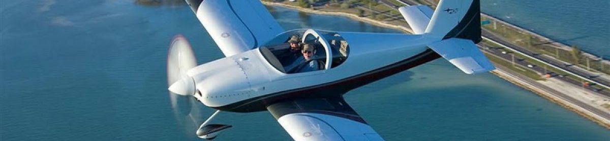
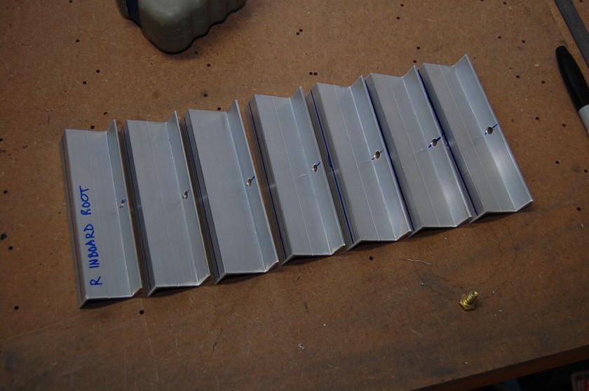
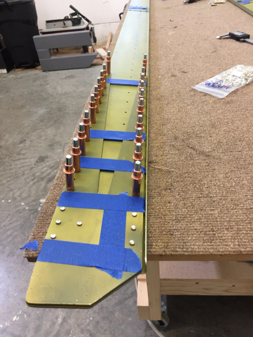
The tank is riveted together just like any other structure with one very important difference which is that sealant is applied between the parts to any seam through which fuel could conceivably leak including every rivet. I roughened all the mating surfaces using a scotchbrite pad. I scored the aluminum well, so the sealing compound will have more surface to grip. I cleaned the manufacturing residues and oils off all the rivets by sloshing them in a jar of solvent and drying them on a clean rag. I cleaned the mating surfaces of the skin, stiffeners and ribs including every surface that the sealer is applied to. It was essential that the surface of the aluminum be clean when the sealer was applied. Not just kind-of-clean or clean enough. Clean. After cleaning, I was careful to not pollute the areas to be sealed. I didn’t even touch them because oils from my skin would affect the bond of the sealant. The tank sealant was mixed as accurately as possible. This was done by weight following the instructions supplied with the sealant. When mixing sealant, I did not mix too much at one time. A batch the size of four or five golf balls was usually enough for one work session. The sealant provided 45 to 90 minutes of working time. I measured weight as accurately as possible and mixed it thoroughly before applying. In order to use the sealant as soon a possible, I had all the work well planned and the tools all laid out. I had the container of Xylene nearby for the frequent tool cleanings that were necessary during riveting. I was able can peel away overflow on areas that I wanted to keep clean by strategically applying plastic tape before spreading the sealant (such as along the areas of the skin that had to mate flush with the wing spar or splice plate). After thoroughly mixing the sealant, I used Popsicle sticks to apply an approximately 1/16″ thick layer to the parts being riveted. In the first work session I riveted on the stiffeners. Back-riveting worked well here, so I spread a thin layer of sealant on the inside of the skin, covering the area the stiffener will contact, and then inserted the rivets into the skin from the outside and taped them in. Then I pressed the stiffener into place. The sealant oozed out around all the stiffener edges. When the stiffener was firmly seated, I back riveted it permanently into place. Even more sealant squeezed out as the rivets set. I cleaned this away, making neat fillets around all the edges of the stiffener with the curved end of the Popsicle stick. Then I dabbed a bit of sealant over every rivet head.

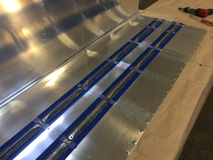
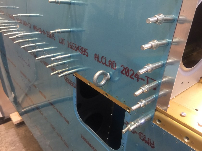
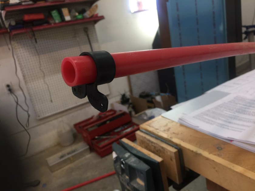
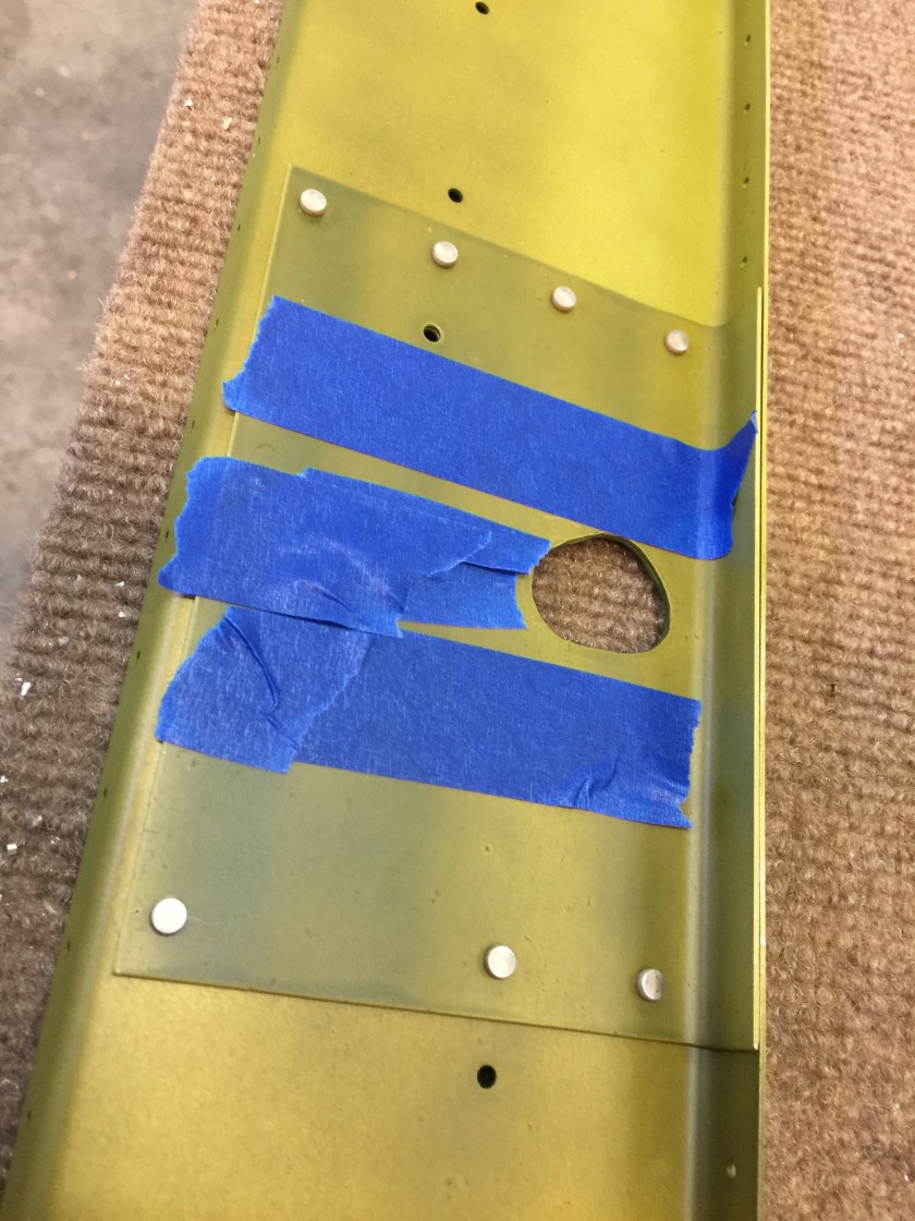
I riveted the drain flange, fuel cap flange and clip to the skin, using sealant in the same way.

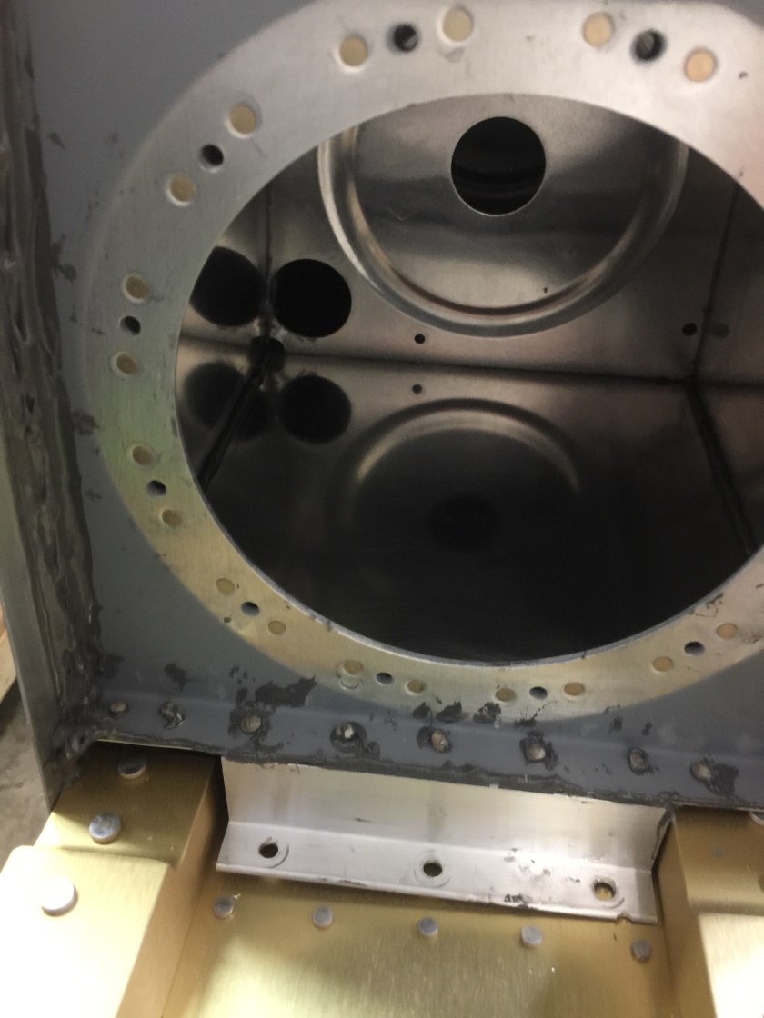
I covered the aft tooling holes in the outboard end ribs by riveting on a small plate. After each session I cleaned everything that I did not want to have a permanent coat of sealant. It was much easier to clean up before the sealant set.

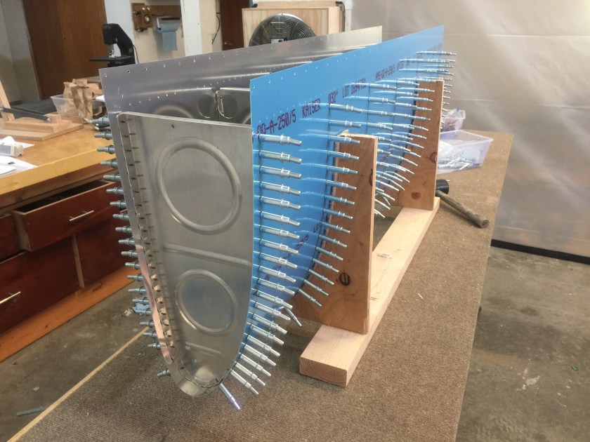
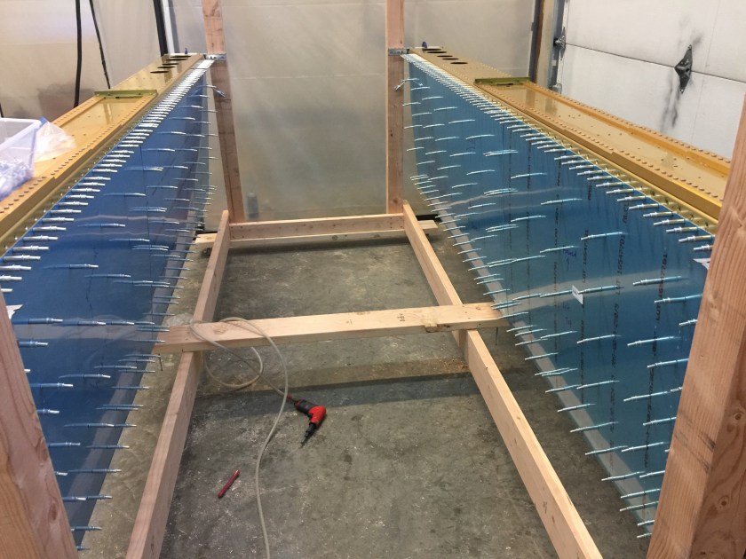
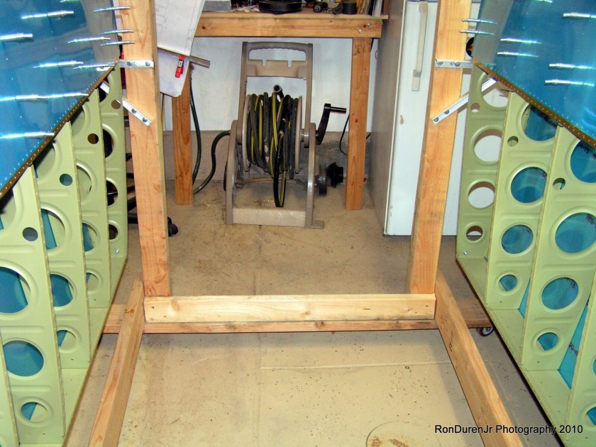
For the next session, I riveted all the interior ribs to the skin working in the “cradle.” When assembling the tank, I clecoed all ribs to the skin to keep the assembly straight. I started riveting with the rib next to the outboard one. After this rib was clecoed in place with sealant I could remove the outer end rib for easy riveting access. I removed the ribs one at a time, applied sealant, and then riveted. When riveting the ribs to the skin I worked from the leading edge to the trailing edge. I inserted the rivets and set them with a squeezer or a rivet gun, as appropriate. I used the Popsicle sticks to form the squeezed-out sealant into fillets in the rib/skin joint. I applied extra sealant to the rivet heads.

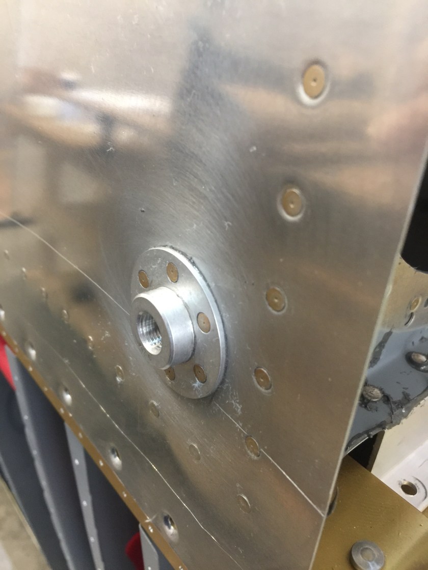
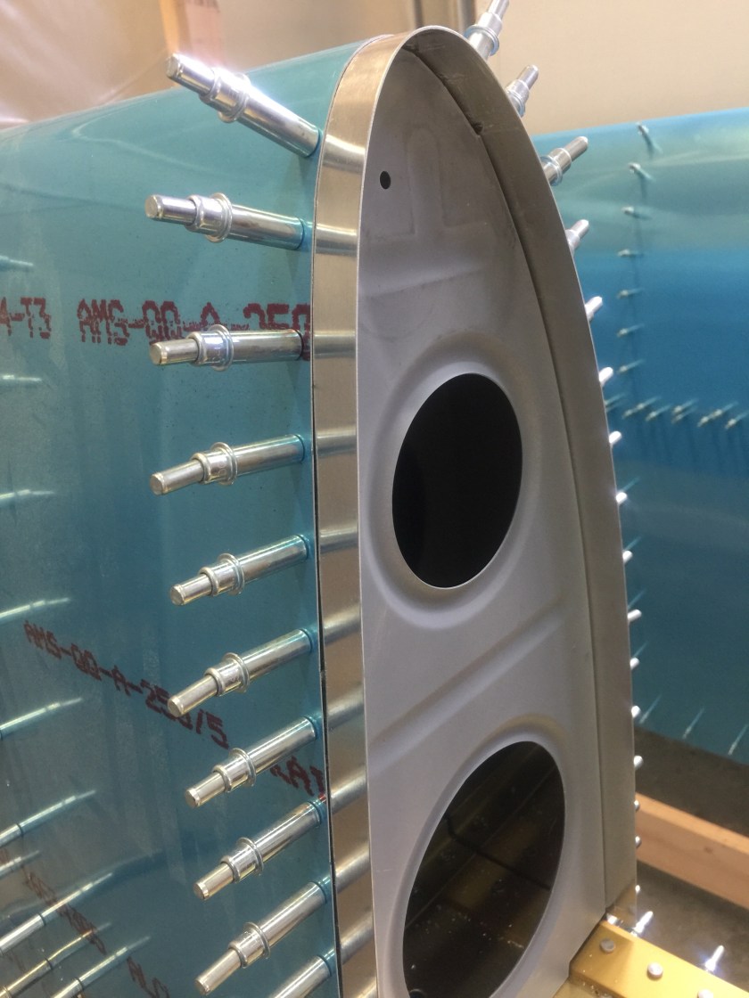
Next, I installed the inboard end rib. After the rivets joining this rib to the skin were squeezed, I installed the bracket and the nose reinforcing plate (fitted to the inside contour of the skin) on the leading edge of the inboard end rib. I put a thin layer of sealant on the sealing surfaces. I then sealed and riveted the other nose reinforcing plate to the outboard end rib used six rivets. I applied a generous fillet of sealant around the inside of the end ribs where they joined the skin, particularly at the very leading edge. Also I made sure the outboard end rib aft tooling hole had been sealed. Finally, I cleaned excess sealant from the rear of the ribs and skin where the baffle would later rest and cleaned sealant smeared on the outer surfaces.

Time: 8 hours.

Assembling the Fuel Tanks

The fuel tanks are also the inboard leading edge of the wing, so they are constructed in a manner similar to the outboard leading edge. However, the tank is removable so the tank ribs can not be permanently attached to the spar. The tank is attached to the wing two ways. Flush machine screws fasten the skin to the spar flanges and bolts hold the fuel tank attach brackets (mounted on the rear tank baffle) to the spar web. The tank is also held to the fuselage by the attach angle.

I first marked a vertical centerline on the forward and aft flanges of all the attach angles.

Then I found the exact lengthwise center of each flange and drilled a 1/8″ hole in one flange of each attach angle. I set one angle aside and drilled a #12 hole in the center of the other flange on the remaining six. When I was done, six of the attach angles had a 1/8″ hole in one flange and a #12 in the other. The seventh attach angle had one 1/8″ hole in one of the flanges and the other flange was blank.

I clecoed the six drilled Attach Angles to the aft side of the pre-punched main wing spar so I could have good access with the drill. I positioned them so the centerline was centered in the pre-punched holes in the spar. I clamped the angles in place and drilled the remaining holes using the spar as a guide.

I then removed the angles and drilled & riveted the nutplates to them, then bolted them in place on the front of the main wing spar.

I clecoed the Baffle to the forward side of the Attach Angles. I checked to see that the centerlines on the angles were visible through the holes in the baffle.

I clecoed the seventh attach angle to the tank baffle between the baffle and the spar. I verified that I could see the centerline on the angle through the holes in the baffle and the spar. I then back drilled through the spar for the three AN3 bolts that attach the angle to the spar. I did not drill the other four holes through the baffle to the angles yet.

I installed the three nutplates on the aft side of the spar.

Next came the fitting of the tank skins to the ribs and rear baffle.

I completed the remaining rib preparation details by bending the flanges to 90 degrees and by fluting the ribs. I used a square to check the flanges and a straight edge to check the ribs for rivet hole alignment.

I then fabricated all of the tank stiffeners. I rounded all the stiffener corners, deburred the edges, then clecoed and finally drilled them to the skin.

I clecoed the tank skin to the baffle (still fastened to the spar) and the wing spar. The fit between the spar, baffle, tank skin and leading edge needed to be perfect. I elongated the holes in the baffle inboard or outboard as necessary to allow the baffle holes to align with the skin holes when it was clecoed to the spar.

I then removed the skin and clecoed all the tank ribs to the baffle. I drilled the rib/baffle/attach bracket holes to full size. I used a drill stop to prevent damaging the spar.

I removed the vinyl from the inside of the tank skin and clecoed the skin to the ribs, baffle and spar.

I then match drilled the tank skin to the Joint plate.

I removed the clecoed tank assembly from the wing, and drilled all the rivet holes to final size. (Doing so off the wing prevented accidentally drilling into the spar).

I machine countersunk the spanwise rows of holes in the tank skin (not the baffle) that attached the skin to the baffle. I kept the baffle in place so that the pilot had a good hole to guide the countersink. This made it easier to slide the baffle into position on final assembly.

I then drilled the spar attachment screw holes and the Joint Plate screw holes to final size using a #19 drill.

Finally I disassembled the tank, marking all parts so they could be easily returned to the same location.

I fabricated the tank attach angle and pre drilled it with the rivet holes.

I clamped the reinforcing plates in place on the end ribs and drilled the attach holes.

I modified the inboard end ribs by cutting the large hole for the access cover using a flycutter on a drill press.

I clamped the cover plate on the rib with the flat forward edge aligned with the stiffener bead, and with an equal distance to the top and bottom rib flanges. I then drilled all of the screw holes, clecoing as I went (making sure the hole for the fuel pick-up was oriented toward the top of the tank). I removed the cover plate and clecoed the reinforcing ring in place.

I drilled all of the platenut rivet attach holes. I removed the stiffener ring, deburred all the holes, dimpled the rivet holes in the rib, and machine countersunk the rivet holes in the stiffener ring for the dimples. I riveted the stiffener ring and the platenuts in place. The gasket under the cover plate would seal these rivets, so they did not have to be set with tank sealant.

I then fit and drilled the fuel cap flange. I used the cap (installed in the cap flange) as a guide for centering the flange in the tank skin opening. I noted that the cap flange had two slight bends in it to help it to conform to the curve of the tank skin. I made the fuel vent clip from a scrap piece of aluminum and drilled it for installation sharing one of the cap flange rivets. I then countersunk the top of the fuel cap flange to accept the dimples in the tank skin.

I centered the drain flange on the prepunched hole and drilled it to the tank skin. I then machine countersank the holes for the attach rivets.

I dimpled the skins and ribs.

I did not prime any area that would be on the inside of the tank because fuel could have an adverse effect on the primer, or (worse) vice versa. At this point, all parts of the tank were deburred, dimpled, and primed as necessary.

Time: 10 hours.

Leading Edge Assembly

I removed the vinyl from the inside surface of the leading edge skin. Then I modified the leading edge skin for the stall warning assembly according to the instructions in the stall warning assembly kit. Then I placed the leading edge skin in the cradle. The ribs were much easier to install when pre-bent to shape in the cradle. Then I clecoed the leading edge ribs into the Leading Edge Skin. I installed the clecoes on the top first; working from the front to the rear. Then I clecoed the bottom, also working from the front to the rear. I then clecoed the Stall Warning mount bracket to the leading edge skin. The most inboard rib was not prepunched with holes and would be installed later. I marked the ribs so they could be reinstalled in the same location.

Then I removed the leading edge assembly from the cradle and placed it on the spar. I put clecoes through the spar into the ribs. I also clecoed the Leading Edge Skin to the wing spar through about every third hole. I slid the Leading Edge Rib in place starting at the lower aft edges of the Leading edge skin. I then back drilled the rear flange from the spar and cleco in place. I marked a line on the Joint Plate 1/2” (with the vinyl removed) from the edge. This line matched up to the holes in the skin, land left 11/16″ exposed to support the tank skin. I pre-bent the Joint Plate to make it fit better around the leading edge. I worked the Joint Plate into place between the Leading Edge Skin and Leading edge rib. I gently tapped the rib and strip with a soft hammer to coax them into place. When the strip was in position I could see the line through the pre-punched holes in the skin. I re-checked the position of the Leading Edge rib by measuring from the edge of the joint plate to the web of the rib. I then drilled all the ribs and the joint plate through the pre-punched holes in the leading edge skin.

I extended the lines for the tiedown eye onto the leading edge. They intersected at the pre-punched hole. I left all of the clecoes in place and moved on to the tank.

Time: 8 hours.

Fitting the Wing Skins

The wings have doublers under the main skin next to the cabin sidewall to add strength and help support the loads imposed by people entering and leaving the airplane. I made the wing walk doubler from AS3-025×9 3/8×26. Then I laid the top inboard wing skin on a bench and slipped the doubler underneath it. The doubler nearly butts against the aft edge of the main spar channel and overhangs the rear spar by about an inch. I aligned the inboard edges and set the forward edge of the doubler 9/16″ aft of the forward edge of the skin. Using the skin as a guide, I drilled all the holes for each rib in the wing-walk doubler.

I clecoed the forward row of holes in the top and bottom inboard wing skins to the matching holes in the main spar. I then clecoed the top and bottom inboard skins to the ribs using a cleco in every fourth hole. I inserted the doubler between the ribs and the top inboard skin.

The main skins overlapped at the eighth rib from the root. The outboard skin fit on top of the inboard one. I gently pulled the ribs into position so the matched holes aligned with the skin holes.

I then drilled all the holes to final size. I start drilling in the upper middle of the panel and worked down and out toward the edges and worked out any slack as I went. I moved the clecoes down one hole (into the drilled holes) and drilled all the remaining holes. I repeated the procedure for the inboard and outboard bottom skins.

I drew a couple of lines on the main skins that intersected at the center of the hole for the tiedown eye. I removed the bottom main skins before fitting the leading edge and tank skins but left the top skins clecoed.

Time: 8 hours.

Preparing the Wing Ribs

I saved time by preparing all the ribs for both wings at the same time.

I began the preparation of the ribs by deburring the edges of the flanges and lightening holes.

I adjusted the rib flanges 90 degrees to the web using a special flange bender.

Incorrect flange angle.

Using the custom tool to adjust the flange angle.

Verifying corrected flange angle.

The forming process leaves ribs bowed, particularly the leading edge ribs. I straightened the webs with fluting pliers. I placed the center of each flute at the midpoint between the prepunched holes and used a straightedge or holes in a wing skin to check for straightness of the line of rivet holes. The straighter the parts, the better they fit.

Comparing the rib straightness with a straightedge.

Using the fluting pliers to straighten the rib.

Verification of straightness after adjustment.

I made provision for running stall warning system wires and wingtip position lights, strobes or landing lights by drilling holes in the ribs for the installation of 3/4″ conduits. I installed plastic grommets in the 7/16″ holes in the inboard ribs of the left wing for routing the pitot tube line.

Time: 6 hours.

Stands and Cradles

Although the matched-hole process eliminates the need for the traditional wing jig, mounting the wing in a stand makes it easier to build. The stand allows access to both sides of the wing and makes it easy to take measurements and assure the wing is straight. The wing has no washout, twist or taper. I made the Wing Stand out of 2X6, 4X4 and 2X4 lumber. A leveling mechanism was incorporated into the ends. The center of the skeleton will sag toward the floor when it is mounted in the stand so to make installing and removing the skins easier, the skeleton is supported in the middle by an adjustable center support. A fishing line is run along the rivet holes in the main spar and the skeleton is raised just enough to bring the rivet holes even with the fishing line along the length of the spar.

A special Wing Cradle was fabricated for storage of the wings:

Additionally a Leading Edge and Fuel Tank Cradle was built to facilitate the assembly of the fuel tanks and leading edges:

Time:  6 hours.

Assembling the Rear Spar

The rear spar assembly is a “Z” section channel, reinforced where it joins the fuselage and at the aileron brackets. I deburred the edges of the rear spar channel, and the doubler plates. I trimmed the ends and deburred the edges of W-707G & D and began the rear spar assembly by clamping the W-707E and W-707F doubler plates to the spar. I used the spar as a template to clamp, drill and cleco W-707E/F to the W-707A spar channel.

I marked and cut out the holes for the aileron pushrods. I clecoed the reinforcement fork and the rear spar doubler plate to the spar channel and drilled the rivet holes to full size. I then deburred, primed and prepared the rear spar components for riveting. Some rivets in the rear spar reinforcements also attach ribs, aileron brackets, aileron gap fairings and the flap braces so I taped over these holes so I would not inadvertently put a rivet in one. I then riveted the components of the rear spar together.

Time:  8 hours.

Main Spar Preparation

The first step in construction of the wing is the preparation of the main spar.  The platenuts for the mounting of the fuel tank are flush riveted onto the spar flanges, 60 on each wing!IMG_5445IMG_5446

Then the tie-down anchor is mounted on the spar web.  This requires the addition of spacers  to compensate for the reinforcement plates on the spar.  The spacers had a tendency to slip and I had to make an extra set when the holes were misplaced.

Time:  8 hours

Wings Kit Arrives

After several weeks of waiting for my Wings Kit it finally arrived on Tuesday, May 16.  Unfortunately it arrived in a huge FedEx semitrailer which could not go up the lane to the shop and it had to be unloaded in the garage.

IMG_5429
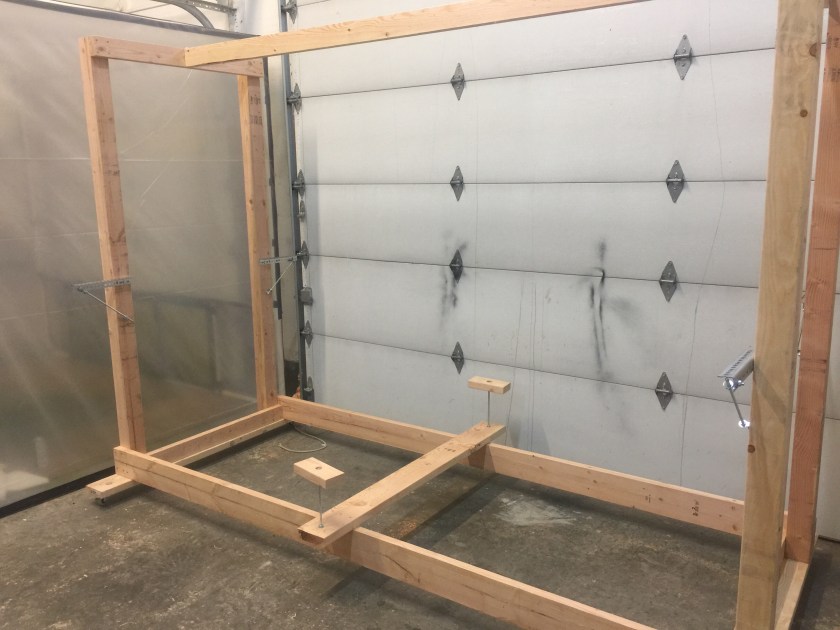
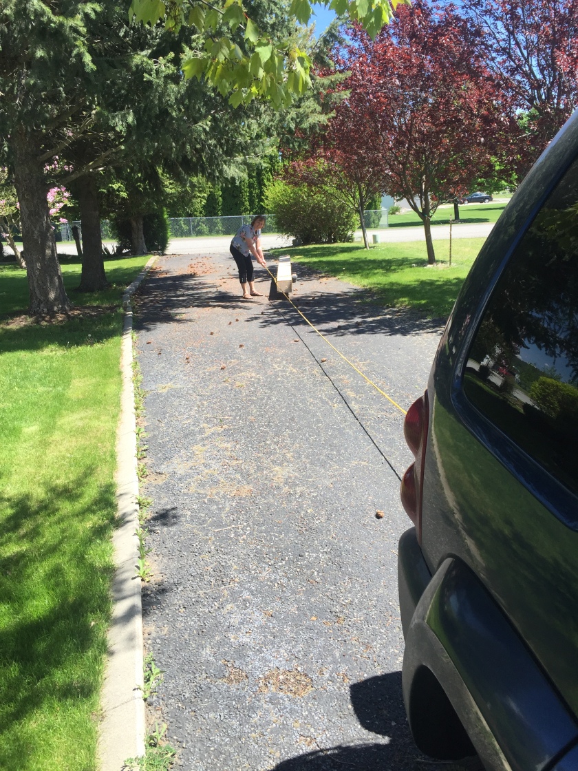
So we borrowed a piano dolly from Rod and Rilla and pulled it up the road to the shop with the Jeep.  Linda navigated while I drove.

Time: 3 hours