Setting the Wing Incidence

With the main spar bolted in place, the next step was the attachment of the rear spars. I leveled the fuselage, both laterally and longitudinally, using the top surface of the F-718 longerons between F-704 and F-705 as a datum surface. I then squared the wing with the fuselage. This was done by measuring from corresponding points on the wing tips to a common centerline point of the aft fuselage.

I equated these distances at the same time checking that the wings had no forward or aft sweep. This was done by dropping 4 plumb lines from the wing leading edges (2 on each wing at inboard and outboard points) to see that they all fell in a straight line. I marked this position with a vertical line at the rear spar attach, on both rear spar and center section.

Checking Sweep

Now the very important incidence angle had to be measured and set. This was done by using a level and spacer blocks as shown in DWG 38. I verified that the fuselage was level and rested one end of a level on the forward spar just forward of the skin butt joint and the other end on a spacer placed directly over the rear spar web. I shifted the rear of the wing up or down to center the level. The spacer size was calculated to provide the desired 1 degree positive incidence angle. I checked several points along the span of the wing to verify the reading. I clamped the root in place and checked the other side in the same manner. See DWG 38, Section H-H.

Incidence Angle

It is extremely important to verify that there was at least 5/8” from fastener center to the edge of the part, in both the rear spar and F-705.

I initially drilled an undersize hole starting with a 1/4” drill. Then I progressively enlarged the hole to 5/16” to provide a close fit for an AN5 bolt. Drilling with a long stiff drill bit was a good idea because it could be held straighter for a truer hole.

Drilling the Rear Spar

The overlapping portions of the F-776 bottom skin were to be screwed to the bottom of the wing when the wings would be installed to stay. Holes for these screws had be drilled now. I used the reference lines to locate the hole positions. After the wing was removed, these holes were dimpled for #8 screws. K1100-08 platenuts were riveted to the inside flange of the root rib.

The F-796A Fuel Tank Attach Brackets were fitted to the fuselage as shown on DWG 38, Detail F. The bracket needed to have the main web adjusted by bending so that it mates flush to the fuselage side and to the T-405 angle bracket on the fuel tank, as shown on DWG 38, Section E-E. I clamped the F-796A angle firmly to the T-405 bracket on the fuel tank. I checked to see that it rested firmly against the fuselage and then drilled the attach holes.

Time: 6 hours.

Wing/Fuselage Assembly

During this phase of construction it was necessary to assemble the wings to the fuselage for a number of reasons including drilling the rear spar/center section attach, finishing the aileron and flap control mechanisms, installing the wing tank/fuselage attach brackets, fabricating and fitting fuel & vent lines, and installation of wing root fairings.

Before installing the wing, I marked on the W-704 the screw locations at each unused rivet space on the bottom flange of the W-710 root rib. I then marked a straight line from the hole location toward the wing tip and made a measured mark 3” outboard from the intended screw location. This allowed me to measure back to the same point on the overlapping F-776 fuselage skin.

Since my shop dimensions were such that the aileron pushrods could not be inserted from the tips of the wings, the W-716 pushrods had to be loosely placed in the wing lightening holes from the root before the wing panels were “plugged-in” to the fuselage.

Wings mounted

Actual installation of the wing panels turned out to be very simple, as the spars had been fitted and drilled at the factory. It was helpful to file a slight bevel on the root ends of the spar to assist getting it started sliding through the slot in the fuselage bulkhead, and to prevent it from scratching and galling the bulkhead bars as it slid through. I supported the inboard ends of the wings when inserting to prevent the bottom of the spar from dragging along the inside of the fuselage bottom skin. As the wings were pushed in near center, I made sure that the fuselage center bottom skin (which overhangs the fuselage) didn’t catch on the wing skin. When bringing the spar into its exact position, lining up the bolt holes in the bulkhead and spar, it was helpful to use drift pins. These were made from hardware store bolts with the ends rounded and tapered on a grinder. Gently driving this lubricated pin into a nearly aligned hole centered the bulkhead/spar hole so that the bolts could be installed without excessive force. I followed the recommendation that 7/16” and ¼” hardware store bolts be used for test fitting to prevent damage to the holes and NAS bolts. I installed the bolts as called-out on DWG 11. For fitting purposes, it was only necessary to install four 7/16” bolts, one top and one bottom for each wing panel. Of course, when permanently installing the wings all the bolts called-out on DWG 11 must be installed.

NOTE: When installing the wing for the last time, I will lubricate the NAS bolts with LPS #2 (available in a spray can). I will not lubricate the threaded portion of the bolt as this would influence the torque wrench reading.

Time: 4 hours.

Wing Tip Installation

The tips were installed with the wings positioned in the wing cradle storage fixture.

I used the aileron control system to neutrally position the aileron, which helped to position the wingtip. I used the aileron adjustment fixture to locate the ailerons in their neutral positions and held them in place with a tape.

I sanded and filed the flange on the fiberglass wingtip so it was an even depth and width all around.

Portions of the aft end of the wing tip had to be trimmed away to provide clearance from the aileron and Aileron Hinge Bracket. I left a gap between the aileron and the tip of approximately 1/4 inch.

I slipped the wing tip into place and pushed it forward so it was tight in the wing leading edge and aligned with the trailing edge of the aileron.

I then drilled the wing tip using a #40 drill, beginning at the leading edge and working to the back and alternating holes from the top to the bottom.

I swung the aileron out of the way and slipped the wing tip rib into place. I then marked the location of the rib trailing edge on the wing tip.

I removed the tip and laid out the rivet lines (top and bottom) 5/16″ from the edge. I then clecoed the wing tip back on the wing and slipped the wing tip rib back in place. The flange edge had to be flush with the wing tip edge.

I located the rib chordwise so it fit without distorting the tip.

I then drilled and clecoed the wing tip rib to the wing tip. I removed the wing tip and machine countersunk it and then riveted the wing rib in place.

The wing tip could be riveted or screwed to the wing. The choice usually depends on what kind of access is necessary to service lights, power supplies, etc.

I decided to use screws and plate nuts to attach the wingtips to the wing. The nut plates were riveted directly to the fiberglass and the wing skins were dimpled to receive the 6-32 screw heads. The fiberglass was machine countersunk to accept the dimples of the wing skins.

Time: 8 Hours.

Installing the Pitot Line and Wires

I installed the pitot line and fittings as indicated on the drawings. I installed the snap bushings in the 7/16″ holes for the Pilot line in the wing ribs, putting the low profile face of the bushing on the flange side of the rib, to ease access to the skin rivets later.

I completed the stall warning assembly instructions. I will complete the last step when installing the electrical system..

Attaching the Flaps to the Wings

I drilled a small hole in the aileron hinge bracket assembly for the flap hinge pin to just go through. I could not get this hole exactly in line with the flap hinge line, but this was a good thing. After drilling the hole in the approximate position, when the hinge pin for the flap is inserted, the pin would spring into position after being pushed all the way through and not be able to come out on its own.

I may have to disconnect the aileron pushrod in the wing to remove this pin after the aircraft is fully assembled. This will allow me to swing the aileron out of the way for pin removal.

Time: 2 hours.

Attaching Ailerons to the Wing

I completely finished the flaps and ailerons before I mounted them to the wing.

I positioned the wing, with the leading edge and the top main skins riveted on, in the wing cradle, leading edge down.

I assembled the aileron pushrods, priming both of them inside and out. I covered the inside by spraying into each end. I then riveted the rod ends to each pushrod.

Making sure the primer was fully cured, I then threaded the rod-end bearings and jam nuts on. I temporarily taped the pushrod where it passed through the rear spar, so when aileron was removed the primer wouldn’t be scraped away.

I install the bellcrank. The bushing in the bellcrank needed to be drilled to final size for the slip fit on the AN4 bolt. The bushing needed to be slightly longer than the aileron bellcrank. It was held firmly between the bellcrank brackets with the bolt. The bellcrank rotated around the bushing, not the bolt. This is the same way that the stick assembly would be done also. I lubricated the bushing with grease when assembling for the final time.

I connected the pushrods to the bellcrank. I used the bellcrank jig provided to set the bellcrank in the correct neutral position. I used a plumb line to position the aileron in the neutral position. I clamped the aileron in this position and adjusted the rod end bearings on the push rod until the pivot bolts at the bellcrank slipped in smoothly. I tightened the jam nuts and labeled the push rod right or left as appropriate. Final adjustments would be made to the second push rod later, when the wing would be installed on the fuselage.

Time: 8 hours.

Flaps

The flaps were the easiest control surfaces on the RV-7/7A to build. The only jigging required was a level, flat surface at least 5′ long and 1′ wide. Easy or not, it was possible to build in an unacceptable twist, so I had to work with care.

I prepared the flap spars by deburring the lightening holes and polishing the edges.

I drilled and clecoed the flap ribs to the spar and then clecoed the assembly to the bottom skin. I made the spacers that go between the end ribs and the bottom of the top skin. The aft edge of the ribs needed to contact the “rear spar” bent into the bottom skin. Thin shims between the aft end of rib and the rear spar were used to achieve this contact.

After making the shims, I drilled the ribs to the rear spar.

I then drilled the ribs to the bottom skin. The line of rivets along the bottom of the spar would hold the hinge that would connect the flap to the wing. I drilled and clecoed on the hinge as well. Pinning the two halves of hinge together while drilling helped to hold the hinge straight.

Instead of dimpling the bottom of the spar, I dimpled the skin and machine countersank the spar, with the hinge clecoed on to serve as a guide for the countersink pilot. The soft hinge did not have to be countersunk or dimpled.

I then fit the top skin to the assembly. I clecoed the top skin to the spar, aligned the holes along the ribs and drilled these before drilling the line along the bottom of the flap.

I fabricated the flap attachment angle. I then fit the flap attachment angle and flap attachment plate to the inboard rib and inboard end of the spar. I riveted the flap attachment angle to the spar with the AN rivets only, leaving the holes that would attach the rib open.

After the necessary dimpling, priming, etc., I began to rivet the flap together. A cradle, made with simple V-blocks like those used in the empennage, was a useful aid. I put the flap in the cradle and removed the spar to gain access to the rear row of rivets that joined the top and bottom skins. I riveted the interior ribs to the skins, but left the end ribs clecoed.

I riveted flap attachment plate and the platenut to the inboard flap rib, then riveted the rib to the skins…I had to set these rivets before “closing the door” by putting the spar in place.

When all the ribs were riveted to the skins, I riveted the spar to the ribs with blind rivets, then riveted the spanwise lines that join the spar and hinge to the skins. I finished by riveting the end ribs.

I expected to trim the upper skin of the flap slightly when the wing would be mated to the fuselage, but for now, I left it untouched.

Time: 6 hours.

Ailerons

The construction technique for RV-7/7A ailerons is similar to that of the elevators. The aileron uses ribs at the ends only; light angle stiffeners support the rest of the skin. The skin stiffeners are provided with the rivet holes pre-punched but not cut to length. The aileron skin is punched to match. These are match-drilled much like the stiffeners in the empennage. I cut and trimmed the stiffeners as indicated. I then located the stiffeners on the inside of the rear aileron skin and match drilled.

I dimpled the stiffener angles and skin. After priming, I riveted the stiffeners onto the skin, using the backriveting method. Following this, I completed the trailing edge bend using the homemade bending brake used on the empennage. The bent skins needed to be straight up to the radius and the radius had to be between 3/32” to 1/8”. I matched the degree of bend to the full size end view drawings. The upper and lower skin just touched the spar when placed in position.

The aileron spar is not symmetrical; the top and bottom flanges are bent to different angles. I checked and labeled each spar for top, bottom, inboard and outboard. I made aileron spar reinforcement brackets from supplied .040” material. Then I match-drilled using spar holes as a guide and clecoed as I went. I clecoed the aileron brackets in place and drill #12 for the attach bolts. I labeled the parts, disassembled , deburred & primed. Making sure that I left the holes that would later attach the ribs empty, I riveted the aileron spar reinforcement brackets on the spar along with the plate nut.

The wide tabs on the top of the nose ribs had no pre-punched holes, they would be match drilled from the nose skin. I fluted the center of the tab slightly to remove distortions from the manufacturing process and used the nose skin holes as a check for straightness. I then clecoed and match drilled the nose ribs to the spar.

I looked closely to be sure that had installed the aileron ribs correctly as they were not symmetrical. The tooling holes were nearer the bottom of the aileron. I clecoed and match drilled the main ribs to the spar.

I clecoed the leading edge skin and the trailing edge skin to the spar with the counterbalance pipe in place. I match drilled the skins to the skeleton including the #30 holes in the counterbalance pipe. The holes along the bottom of the spar were opened to #30 for the blind rivets. I then removed the trailing edge portion and re-clecoed the leading edge in place with the counterbalance pipe in position. Using a long 1/8” drill, I went through the lower hole that attaches the nose rib to the spar and drilled through the tab on the rib into the counterbalance pipe.

I disassembled the parts, deburred, dimpled and primed. I machine countersank the holes in the counterbalance pipe.

Attach the nose ribs to the counterbalance with blind rivets. Bend the tab on the nose rib just enough to clear the rivet tool.

I clecoed the leading edge skin to the counterbalance/rib assembly and rivet the nose ribs to the spar. Then I clecoed the aft skin to the spar. Leaving out the main ribs and the clecos along the bottom of the spar to allow access to the inside I riveted the leading edge skin and trailing edge skin to the top of the spar. Then I riveted the nose ribs to the the top half of the nose skin only, inserted the main ribs and riveted them to the spar and top of the aft skin. Then I installed the aileron brackets.

I flipped the assembly over , clecoed it together and weighted it down on the flat work surface. I blind riveted the counterbalance pipe to the leading edge skin. Checking that the aileron was flat, I riveted the bottom side of the nose rib to the skin. I then riveted the bottom side of the main ribs to the aft skin. Lastly, I blind riveted the leading edge and aft skins to the spar.

Time: 8 hours.

Riveting the Wing Skins

There is a definite order in installing the wing skins. First, the leading edge (built off the wing) is installed. Then the top main skins are installed. The wing is then rigid enough to remove from the stand and install the ailerons, flaps and work on the internal details. After that is complete, the wing is laid, top down, on a large table and the bottom skins are riveted.

WING SKIN PREPARATION AND ASSEMBLY

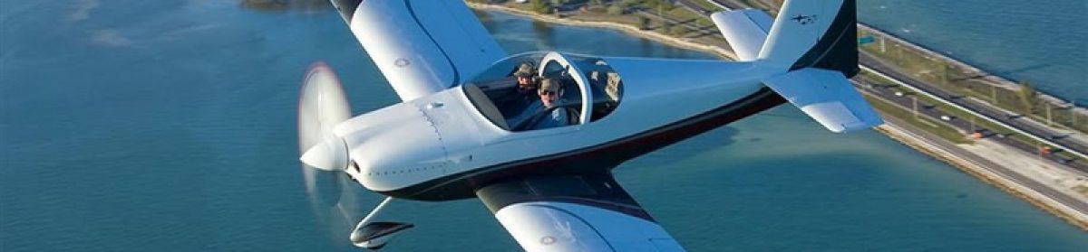
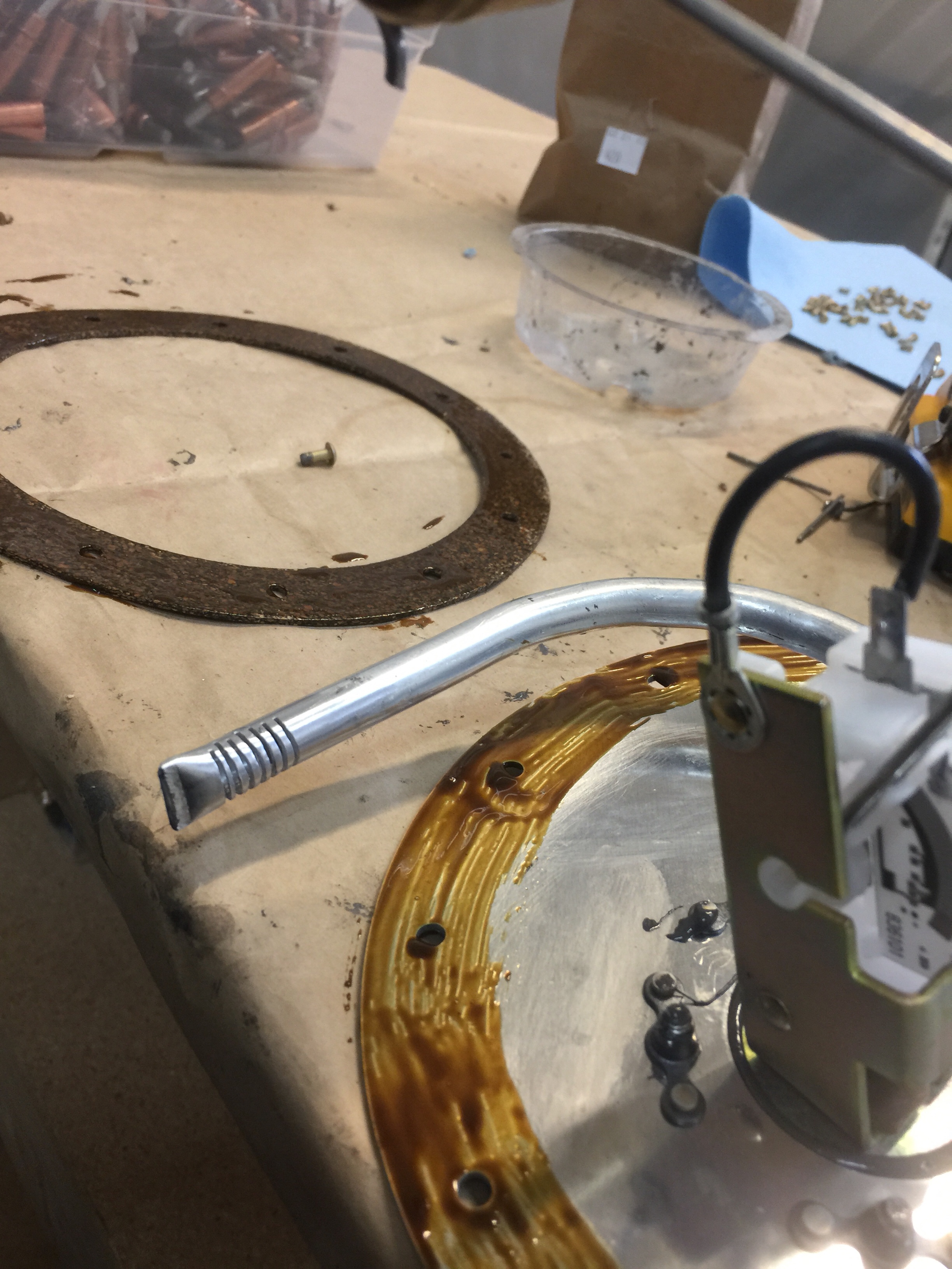
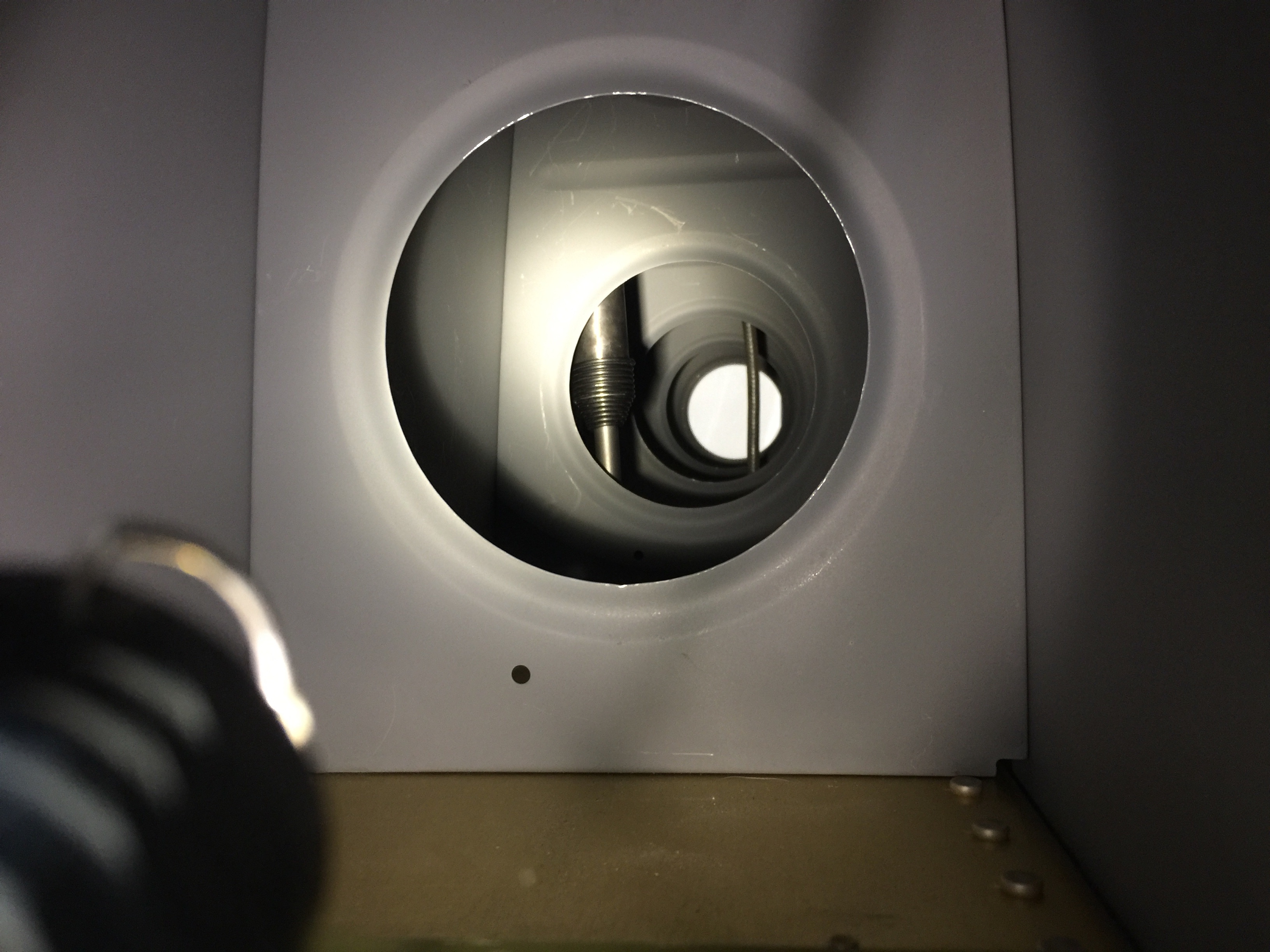
I removed the skins, deburred and dimpled them. I completed Steps 5-6 of the Stall Warning Installation Instructions by deburring and dimpling (the parts are riveted when riveting skins). I prepared the skeleton while it is still fastened to the stand. I drilled a 7/16″ hole in the left outboard leading edge skin and the left main spar flange for the pitot tube fitting. I dimpled the ribs with the pneumatic squeezer. The 0.063 main spar channel was too thick to dimple so it was machine countersunk.

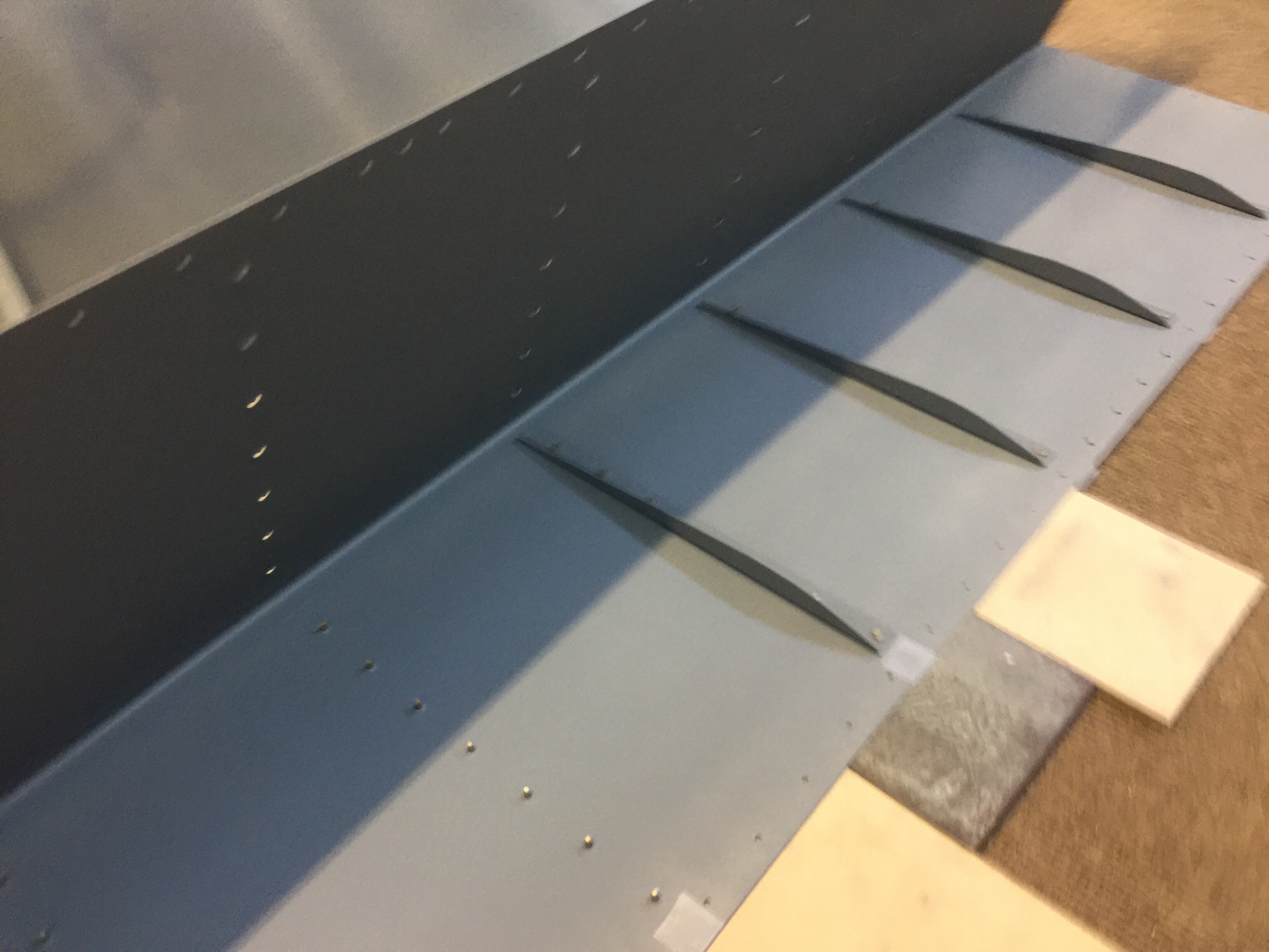
I dimpled the 0.040 rear spar and “touched up” the dimpled holes slightly with the microstop countersink. This “touch up” operation removed just a small amount of metal to make the skin dimple fit better. I drilled the splice plates for installation of the platenuts. I then deburred all holes. I dimpled the screw holes and the rivet holes for the rib and the platenut attachment. The holes for attaching to the rib and skin were slightly touched up (like the rear spar) to gain a better fit between the skin, the splice plate, and the rib. I clecoed the main skins to the wing skeleton. The skins overlap, outboard skin over inboard. This means that the doubled skins would protrude above the aft edge of the tank skin at the spar. I filed the corners of these skins, starting at a point 3 or 4 inches from the corner, making each of them progressively thinner toward the edge. This formed a sort of “scarf joint” and lowered the forward edge, making a clean joint with the tank skin. It was NOT necessary to scarf the whole width of the skin, just the corner.

I had arrived at the point of no return; the point where things started to go together permanently. I made a close inspection to assure that everything was clean and proper before continuing.

ASSEMBLING THE WING LEADING EDGE

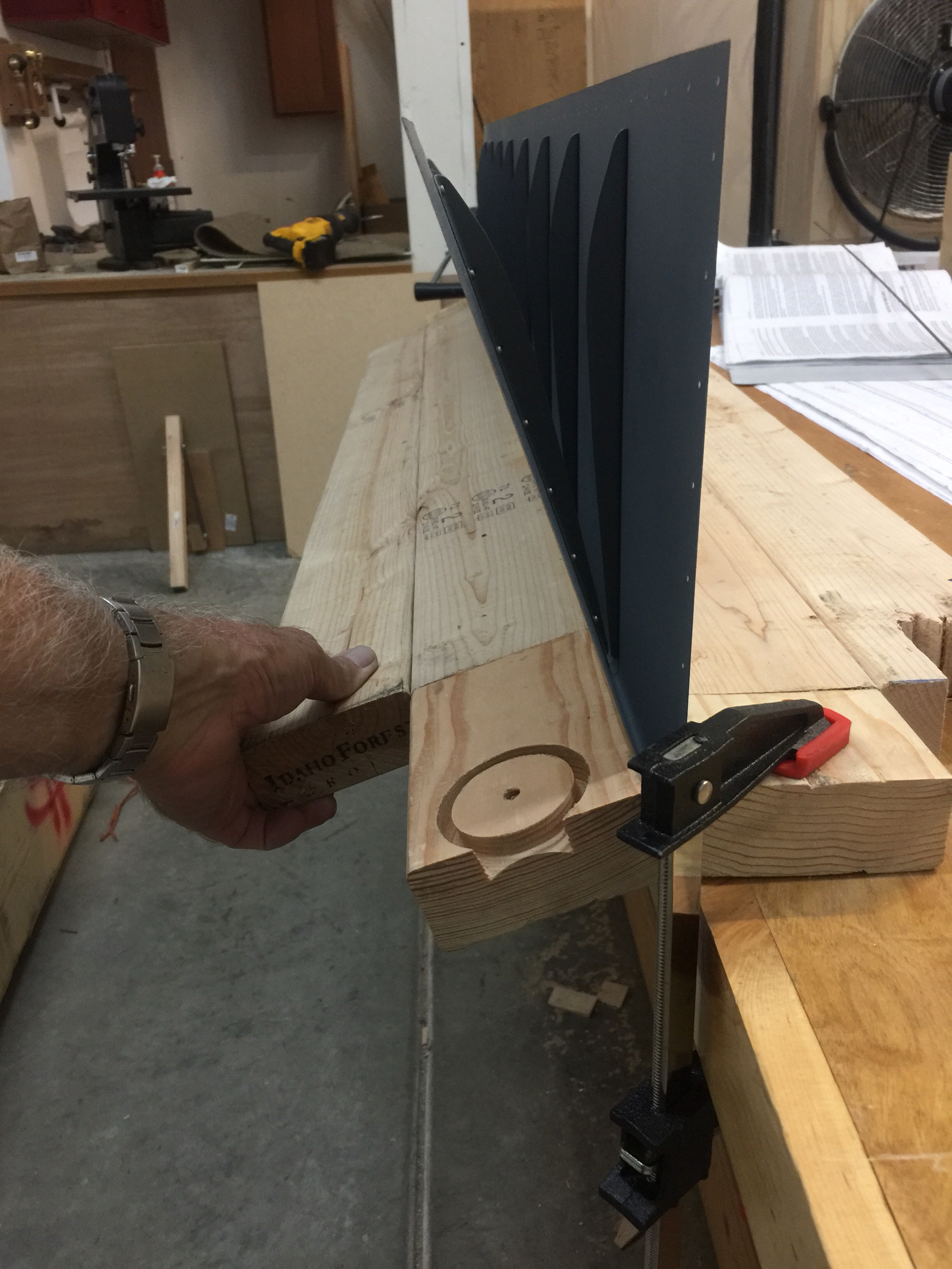
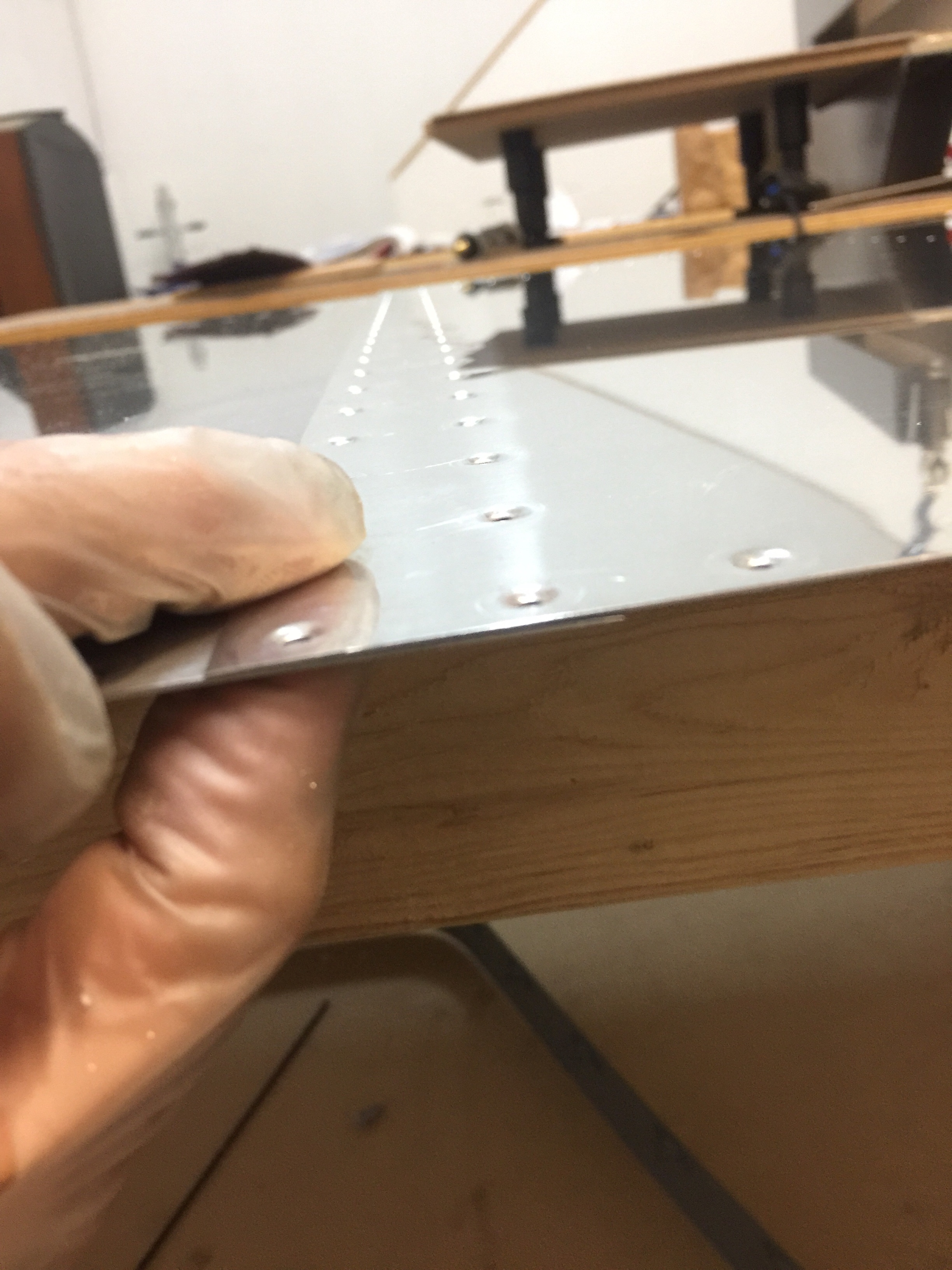
I riveted the Leading Edge Assembly by fitting the skin into the cradle and then clecoing in the ribs and the splice plate. After making sure that the holes at the aft end of the ribs are exactly aligned, I riveted the aft most rivets on the top and bottom using a rivet squeezer. I finished the riveting by working from the rear towards the L.E. one hole at a time.

INSTALLING THE LEADING EDGE

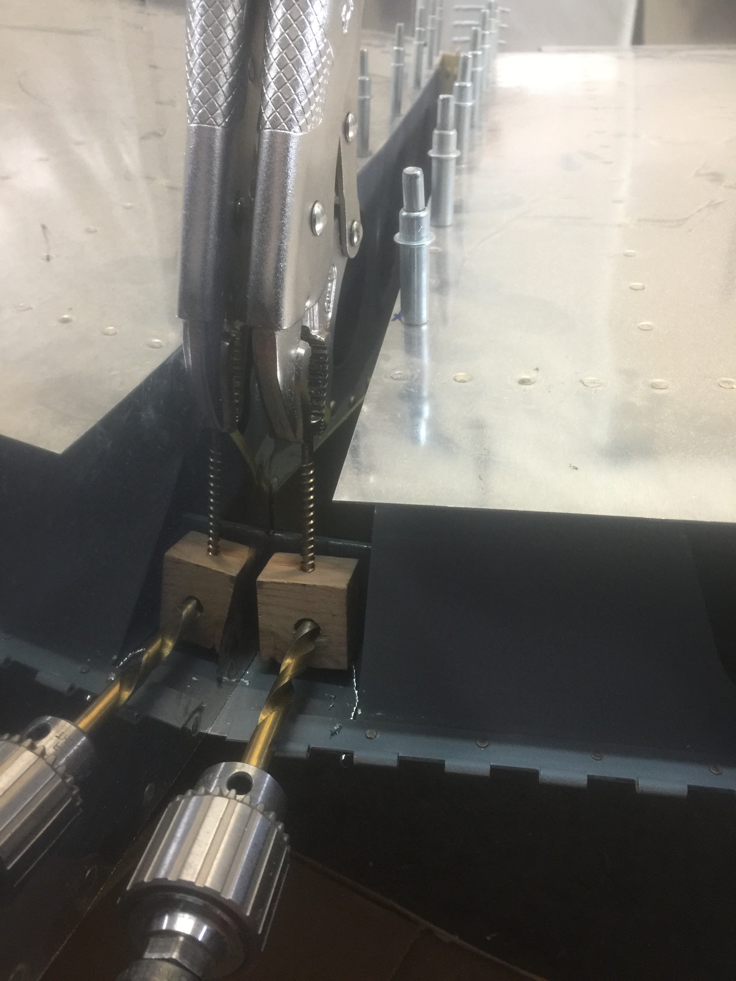
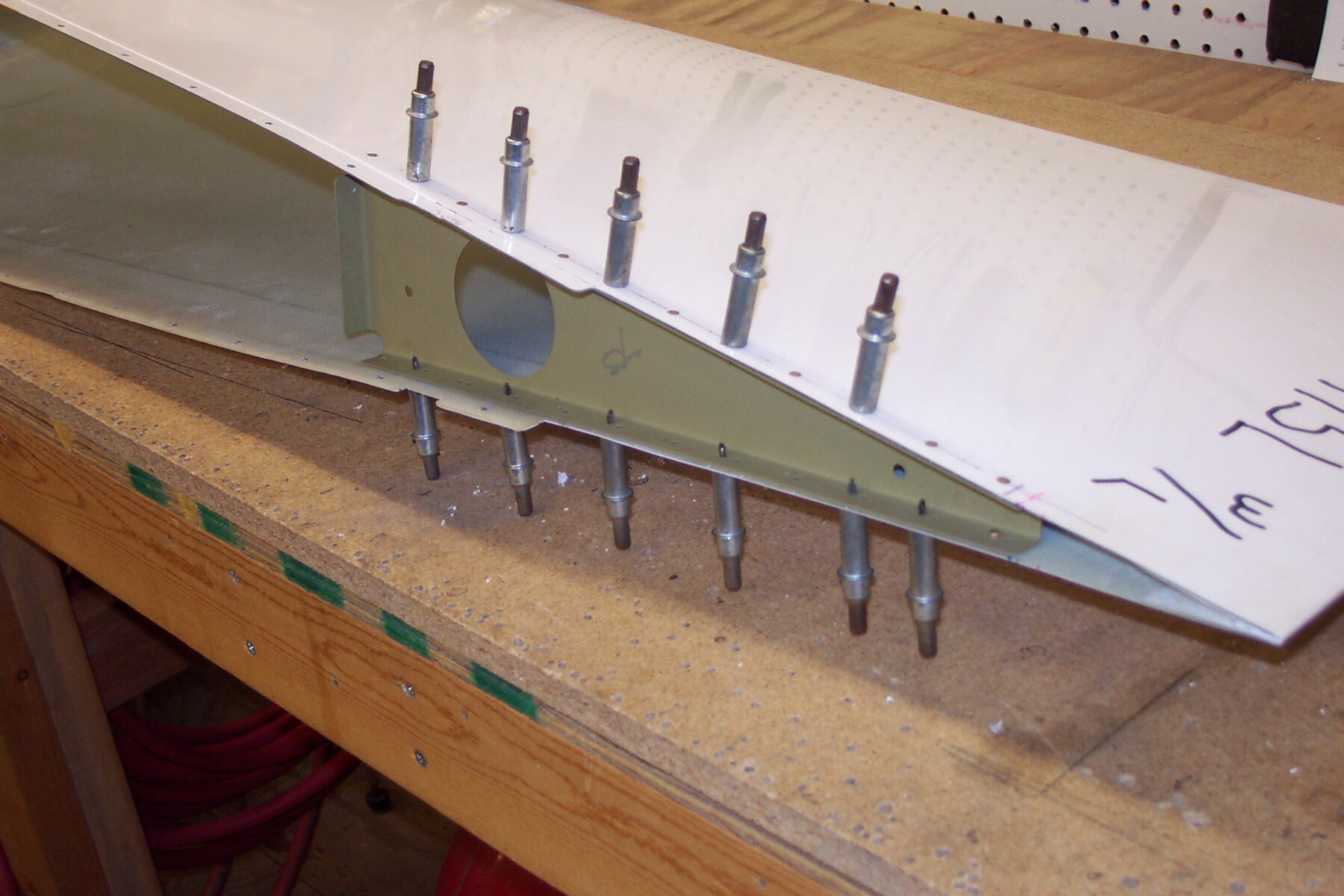
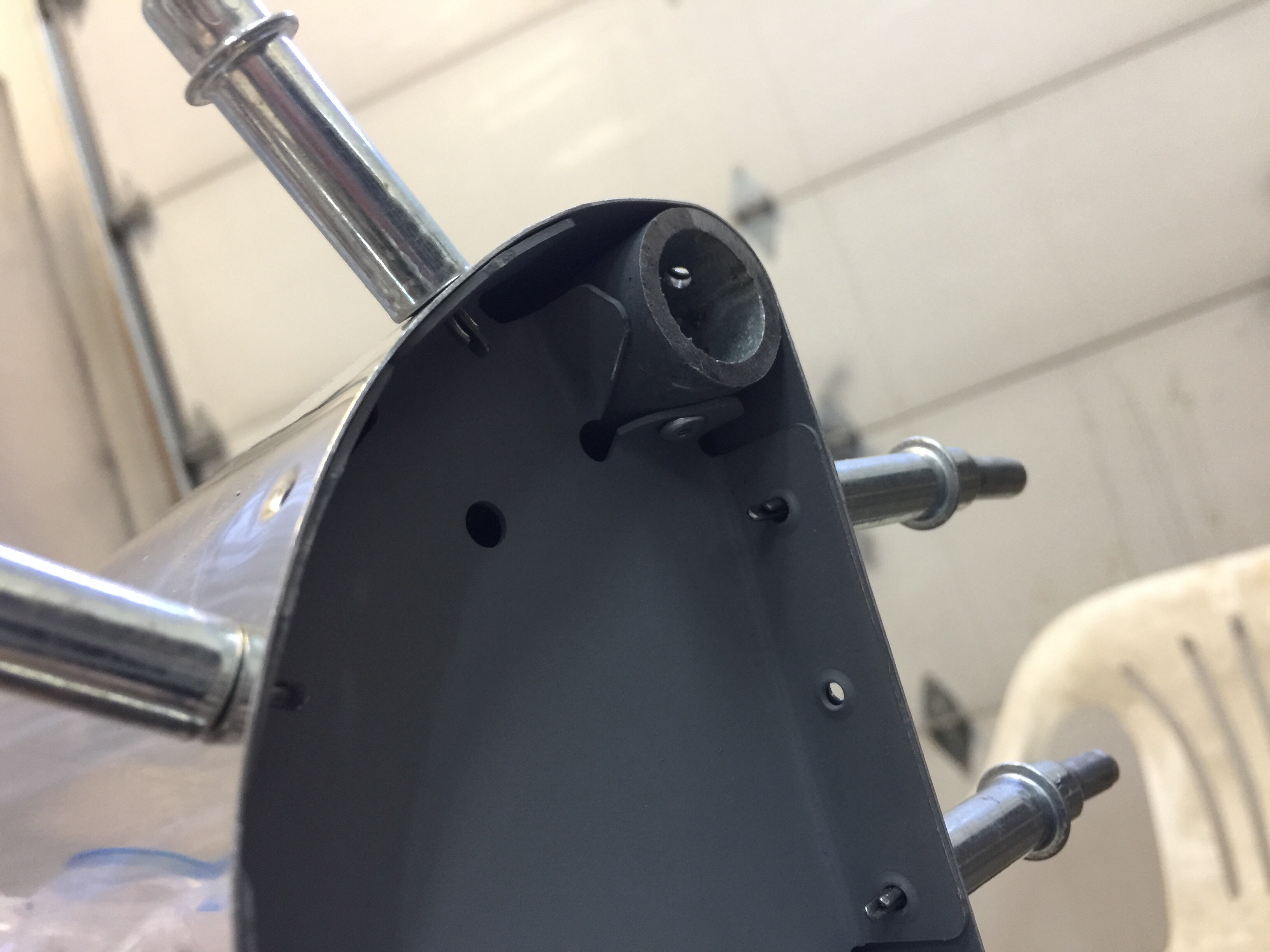
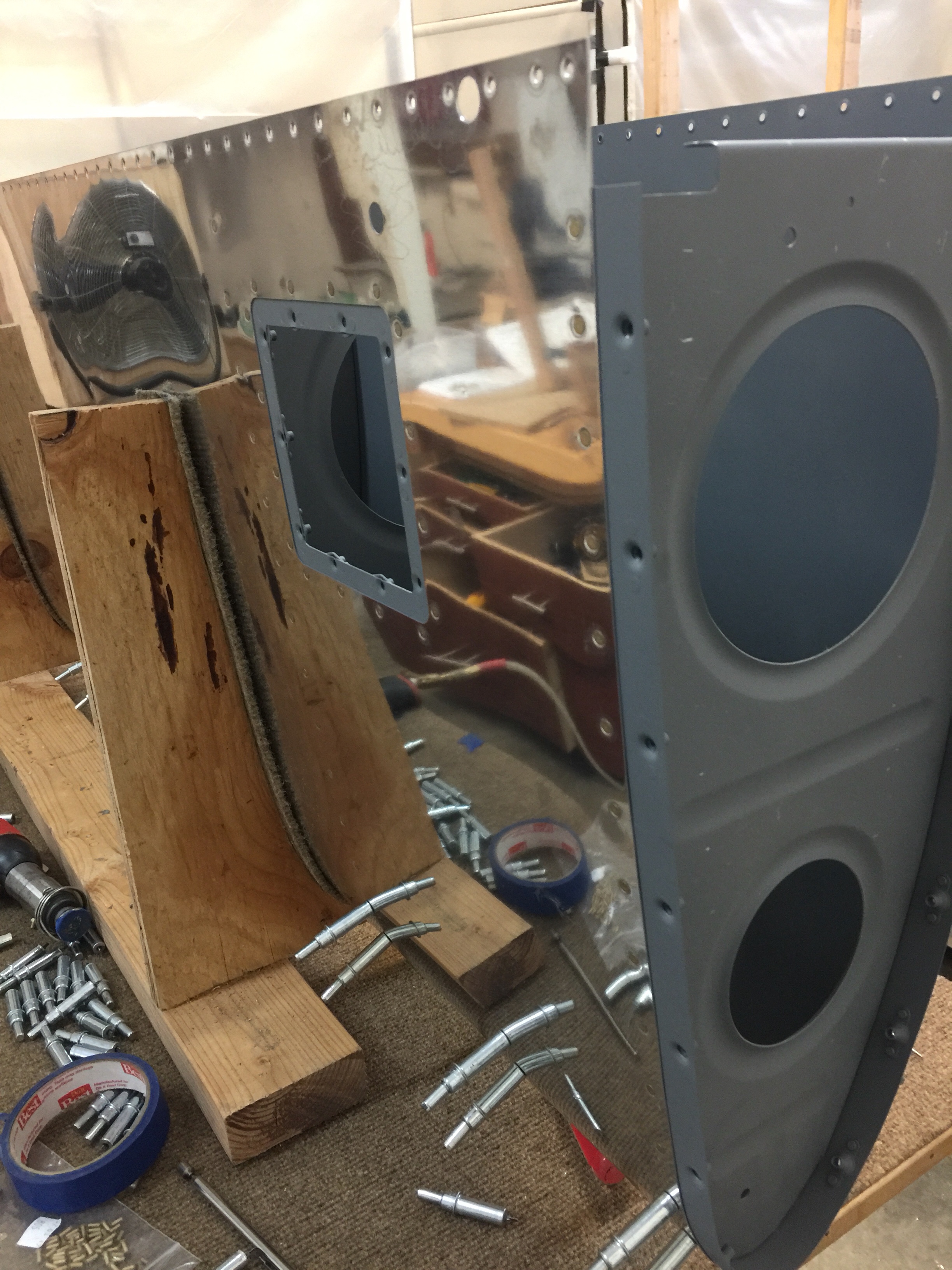
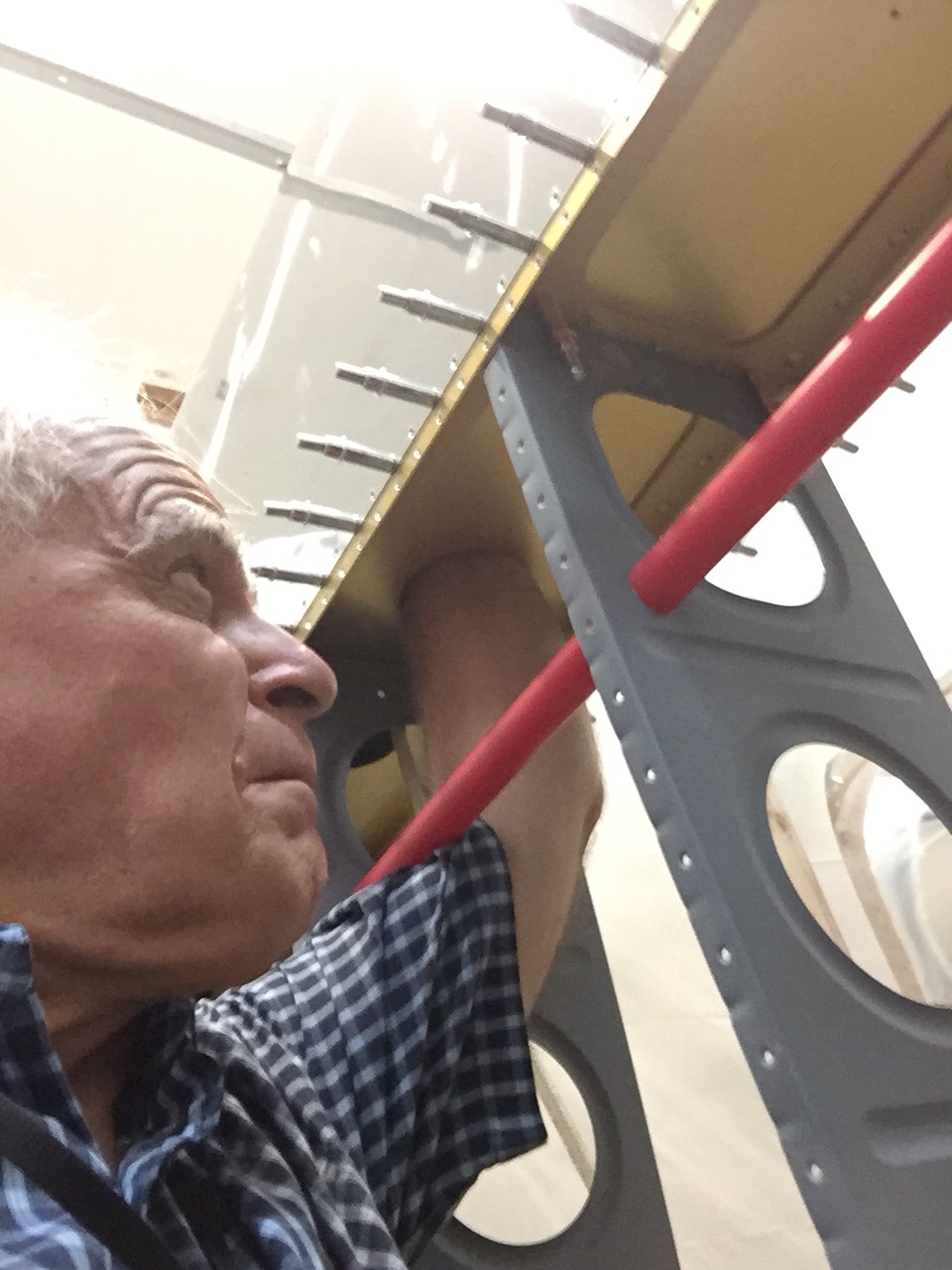
I installed the leading edge assembly on the wing skeleton. While the main skins are off, there was just enough room to reach in and rivet the rib flanges to the spar web. This required an offset rivet set. I remembered that the outboard ribs are riveted together in assembly with the spar web. After I riveted the ribs to the spar, I riveted the spanwise row of rivets, top and bottom, along the main spar web, using a rivet squeezer.

I then installed the fuel tank on the wing, with screws in every other hole, top, bottom and around the leading edge. I installed about half the bolts in the Z-brackets.

RIVETING THE TOP SKINS

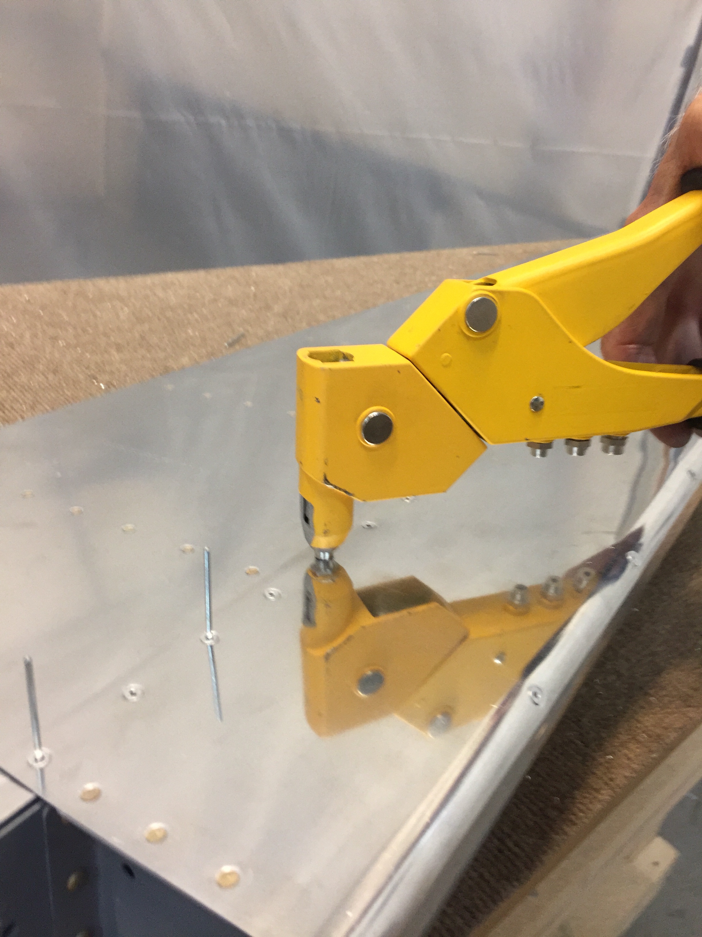
With the outboard leading edge riveted in place and the tank installed it was time to rivet the top main skins. While it would have been possible for one person to install the first set of main skins, it was much easier with the help of my wife Linda. I riveted the inboard skins first, because the outboard skins overlap them. I began by clecoing the inboard skin in position (wing walk doublers, too) and started riveting. To assure maximum skin tightness, I riveted from the center rib of each skin outward towards the root and tip. I did this on both the inboard and outboard skins, and saved the double row of rivets at the lap joint until last.

INSTALLING THE AILERON BRACKETS

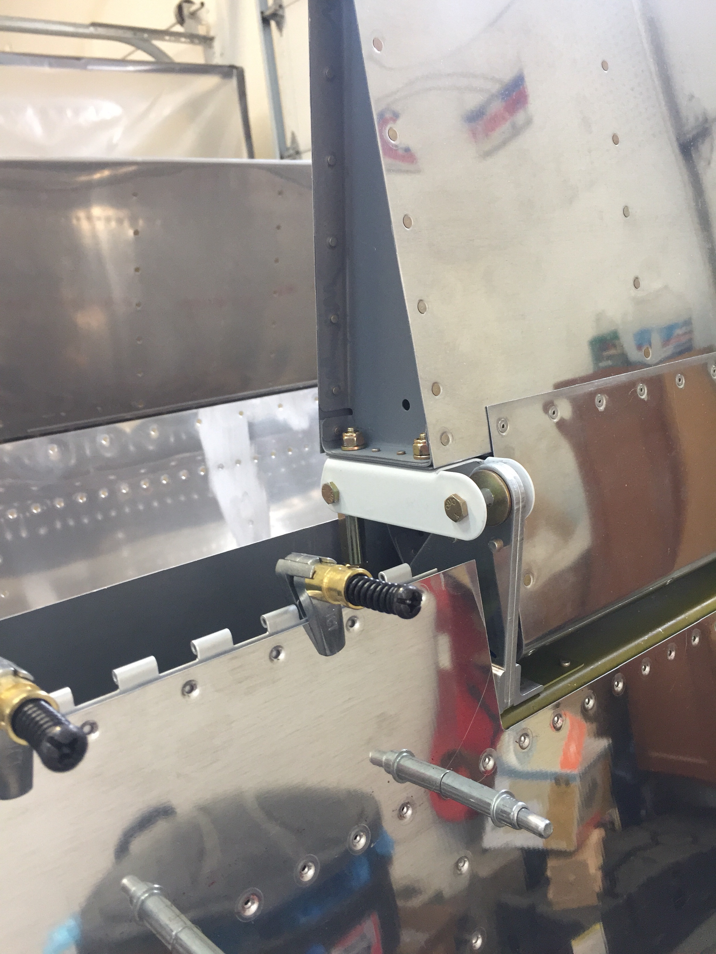
I assembled the Aileron bracket assemblies and installed them on the rear spar by lining up the matched holes, drilling, deburring, and riveting.

INSTALLING THE FLAP BRACE AND AILERON GAP FAIRINGS

I drilled, deburred, and dimpled where required, and riveted the flap brace to the rear spar. I drilled the aileron gap fairing to the rear spar. I drilled, deburred, and dimpled where required, and riveted the aileron gap fairing to the rear spar.

RIVETING THE BOTTOM SKINS

The bottom skins were riveted by beginning with the inboard skin and riveting it to the rear spar, between the inboard wing walk ribs. This meant pulling the skin back until I could reach the rear spar with a bucking bar. While it is possible for one person to rivet the bottom skins working solo if they use some sort of tape/rope/clamp system to peel the skin back, I found the job easier with a helper. I had be careful when pulling the skin back. If I were to have tried to bend it too sharply, I would have gotten an unsightly, and irreparable, kink. I worked in an “L” pattern, riveting toward the tip along the rear spar, then about halfway up the wing rib. Before the skin was riveted all the way to the main spar, I moved to the next bay and repeated the process. After the second bay was partially riveted, I completed the first. The riveting got much easier as I moved forward, because of the improved access through the larger holes in the ribs and the inspection openings. Once the inboard skin was riveted, the outboard was installed the same way, beginning on the inboard rib and working toward the tip. I laid the skin back down after every bay or so and checked to see that all the holes in the skin and the skeleton were still aligned and that the skin was not “creeping” outboard.

Time: 12 hours.

Closing and Finishing the Fuel Tanks

Since I am using a float type fuel sender, I adjusted and checked it before I closed the tank. I made an electrical check with a multimeter which showed about 32 ohms when the sender was in the “full” position and about 240 ohms in the “empty” position. I installed the fuel pick-up tube and positioned it so it lay on the bottom of the tank. I used a small amount of sealant to seal the rivet holes. I then double checked all final details before installing the baffle and closing the tank. I checked that the tank vent line was in, and that its outlet was at the tank high-point. I checked the vent line bulkhead fitting to see that it was tight and that it had been installed with sealant. Once I was sure that everything was in order, I applied sealant to the tank skin from the rivet holes forward. Upon installation the baffle acted as a squeegee and the bead of sealant was pushed ahead as the baffle was moved forward. I used a maximum of 3/16′ bead of sealant. I put a bead of sealant along the inside edge of the flange on each end rib. I put a heavy glob of sealant where each corner of the baffle would meet the end ribs (this is one of the most common locations for leaks). I put a very thin smear of sealant around each of the rivet holes on the back flanges of the fuel tank ribs. I noticed that the tank ribs had a larger notch in the lower corner than in the top corner at the rear flange. This was to allow any water that might condense in the tank to run to the low point and be drained. I was careful not to allow the tank sealant to block off this path. With the tank sitting in the cradle, I installed the rear baffle assembly by dropping it straight down onto the rear flanges of the ribs. I put a cleco in every hole of the fuel tank skin to baffle joint. After clecoing, I inspected the skin to see if it was pillowed out between the clecoes. The contact surface of the tank baffle flange required pressure to force out the excess sealant. The easiest way was to apply cleco clamp between each set of rivets and squeeze out the excess. I twirled the closed end blind rivets in sealant and set them in the top and bottom baffle-to-rear rib-flange holes. The fuel tank attach brackets were installed last. I checked to be sure that the platenuts had been installed on them because it would have been much more difficult to do it once they had been riveted to the tank. I put a very light smear of sealant over each hole for mounting the fuel tank attach brackets. I noted that the brackets on each end of the tank used solid rivets, not blind rivets. While double-checking with the drawings, I clecoed each bracket in place. I was careful to get them oriented correctly because they would have been shortly very difficult to change. I installed the blind rivets in the fuel tank attach brackets after twirling them in sealant. I finished all of the riveting and cleaned the excess sealant off the tank.

To mount the cover plate I used an 1/8” inch thick bead of fuel tank sealant between the cover plate and the inboard rib. I dabbed a small blob of sealant on threads of each attach screw, insert them into the holes, and tightened them sequentially until the sealant bulged evenly about 1/32” from underneath the perimeter of the sender plate. The sealant also formed a small gasket around each screw head.

I installed the Fuel Level Sending Units with sealant using the appropriate hardware. I did not install the rubber gasket supplied by the manufacturer. I used the same procedure for sealing the sending unit as was accomplished above. A continuous electrical path was necessary between the airframe and the sender plate so I made sure that at least one of the screw heads was making metal to metal contact with the outside of the sender plate. I conducted a final electrical continuity test for the sender units with an Ohm Meter by probing the tank body and the sender center screw to ensure proper operation. I waited 48 hours and then conducted a fuel tank leak check using the FUEL TANK TEST KIT obtained from Vans Aircraft.

Time: 16 hours.