Hired a wrecker truck to move the airplane to my hangar at Felts Field.
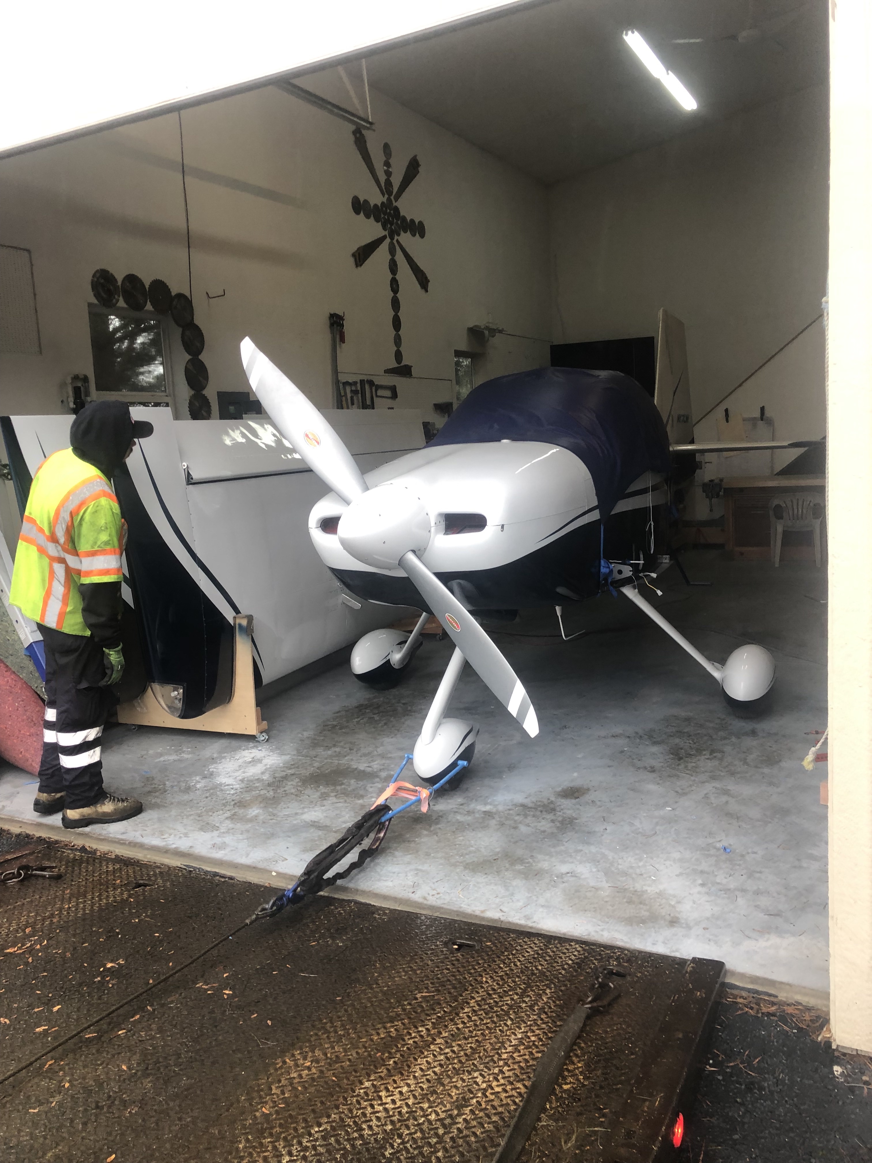
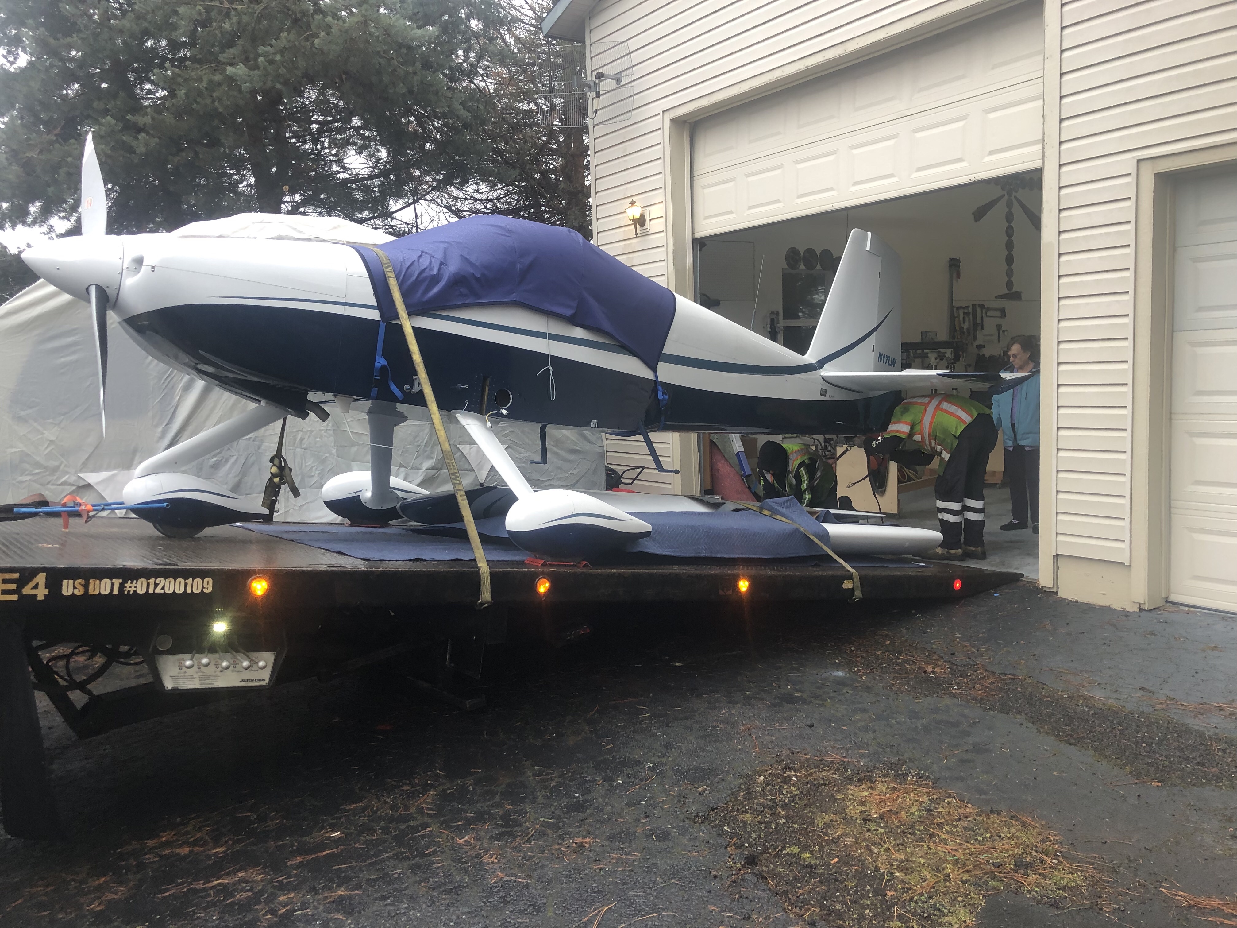
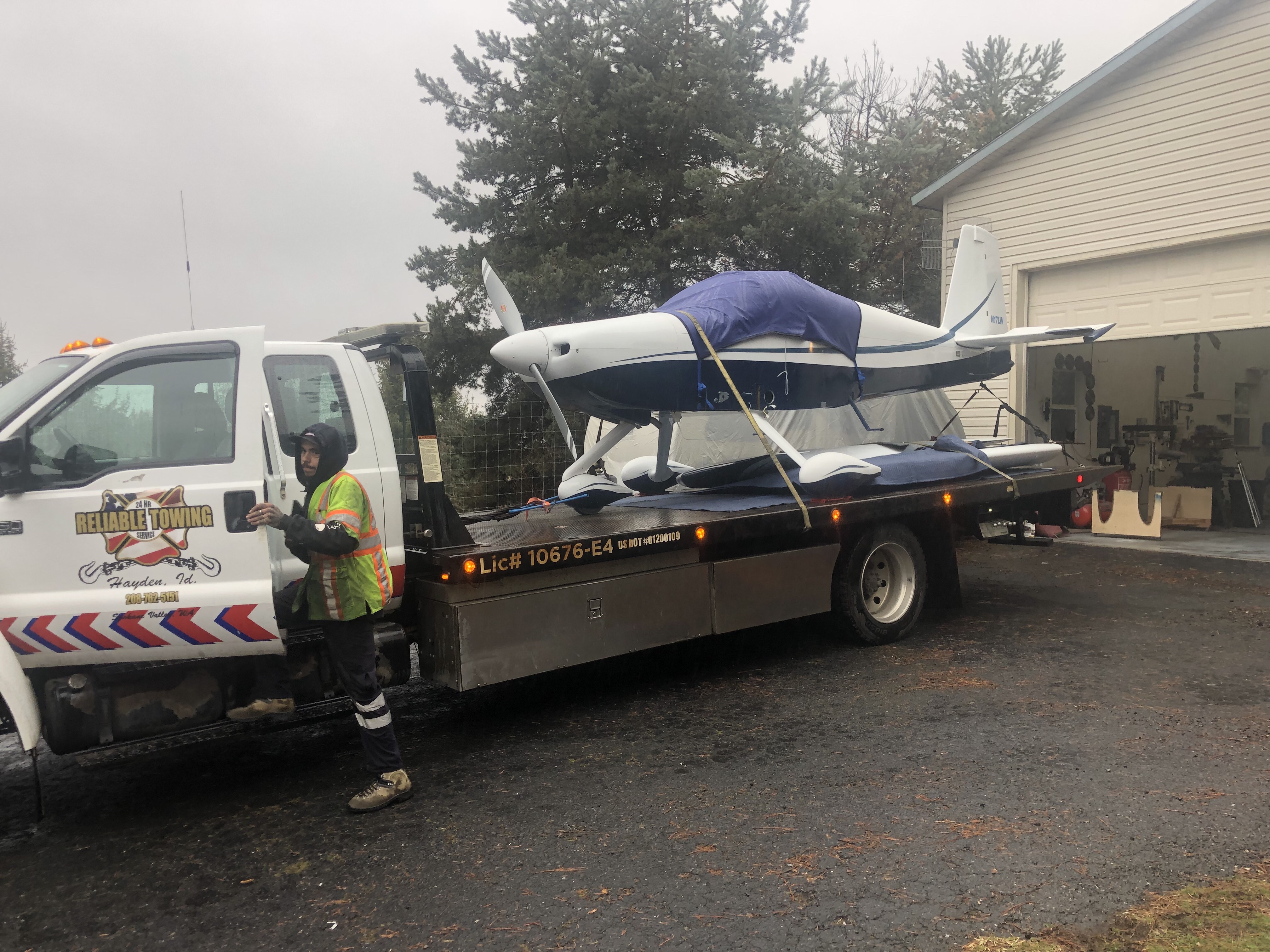
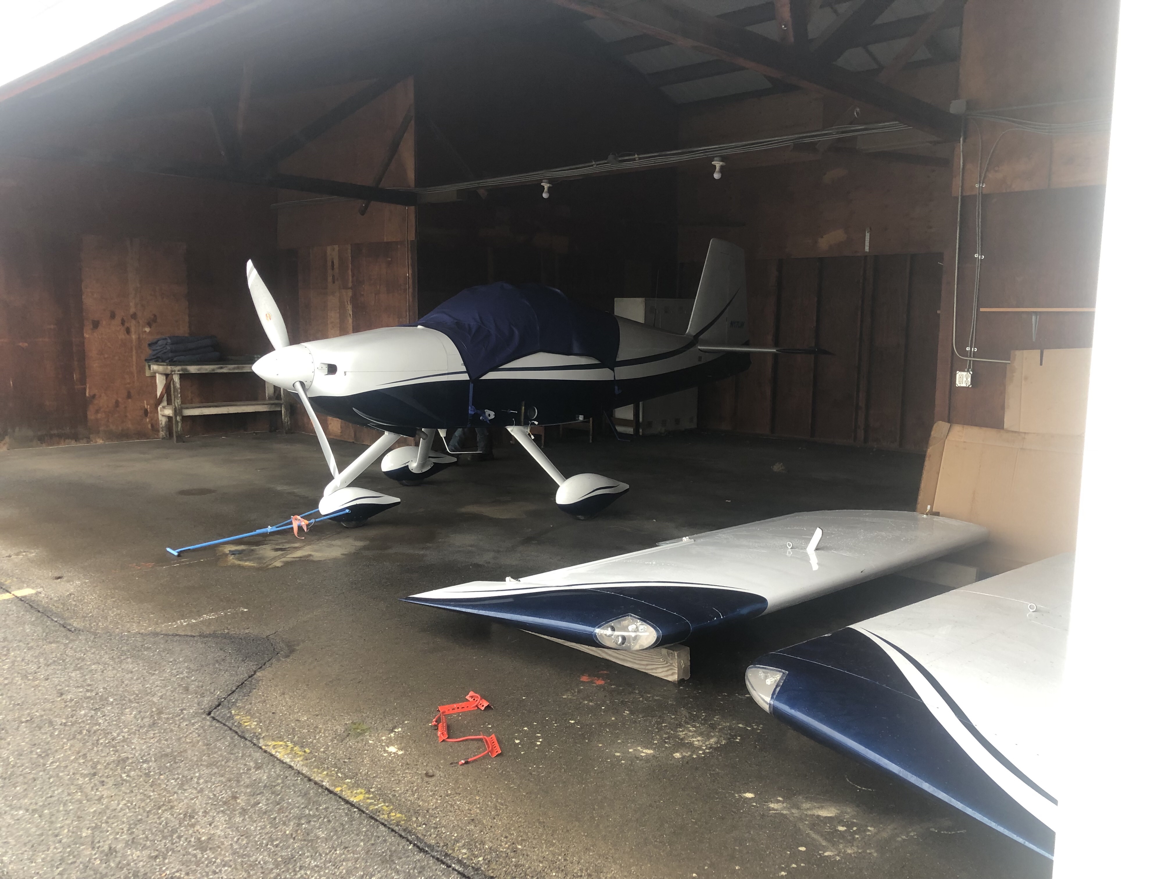
Time: 4 hours.
Hired a wrecker truck to move the airplane to my hangar at Felts Field.
Time: 4 hours.
The N-Number decal was applied to both sides of the rudder.
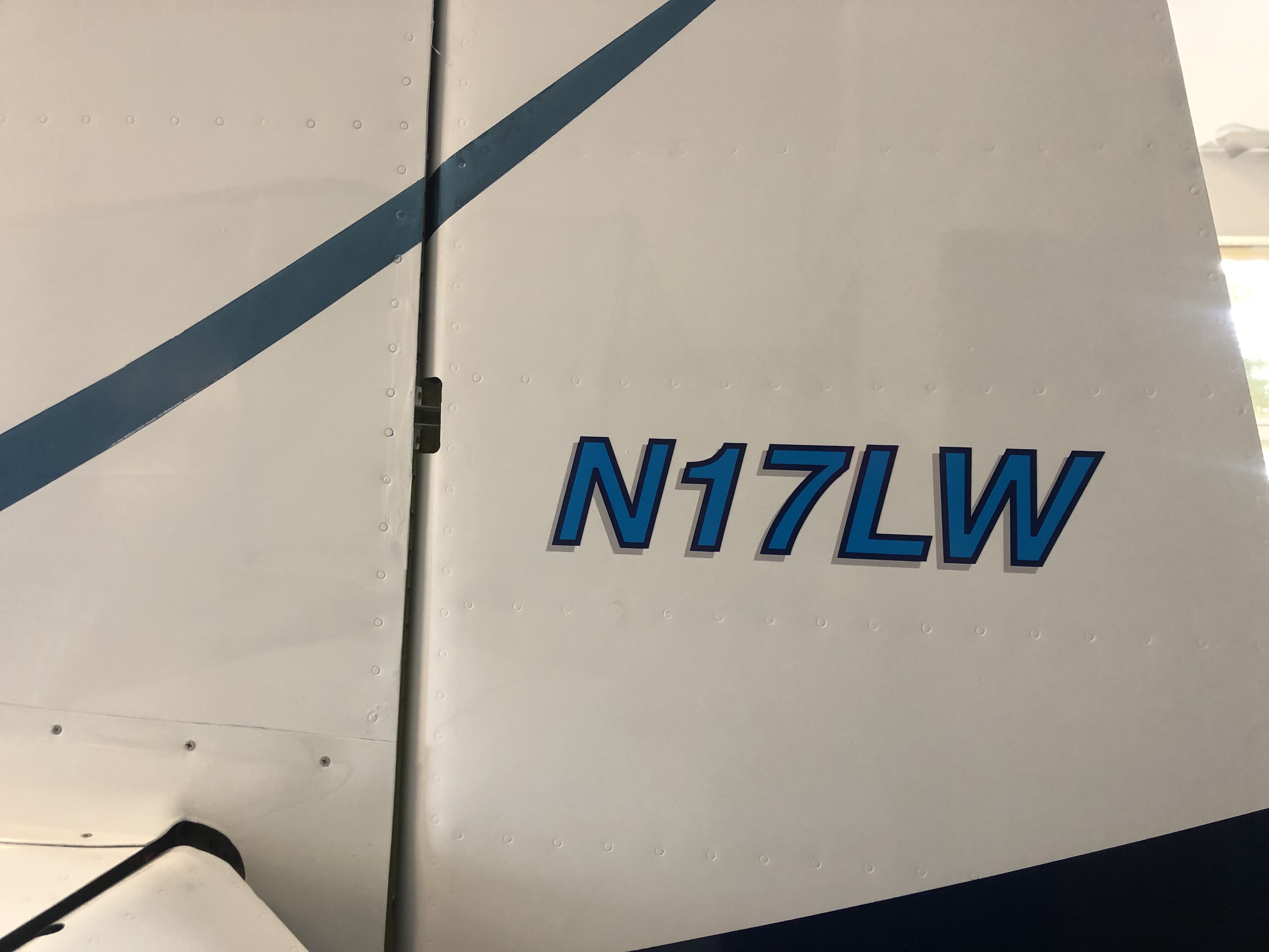
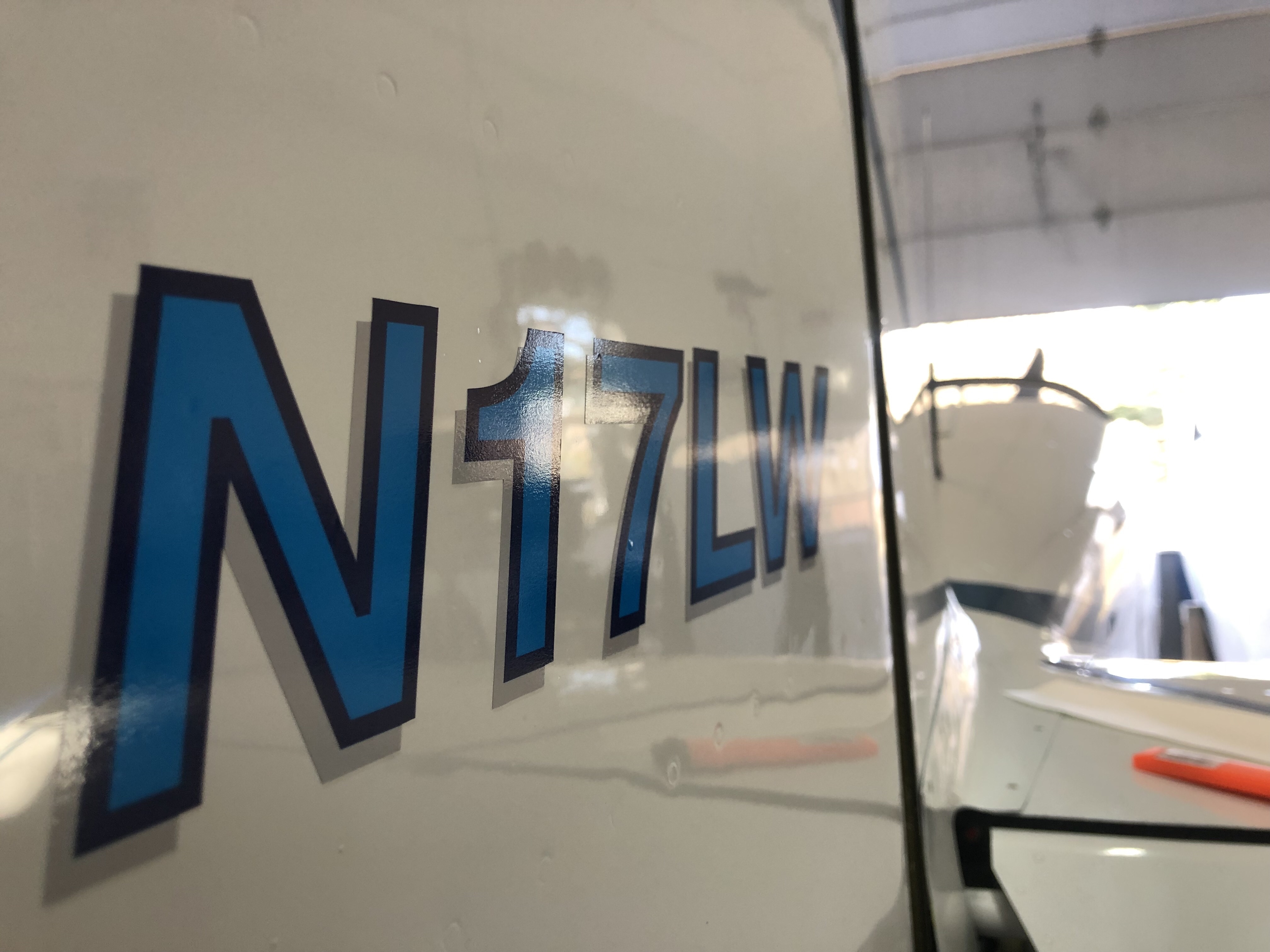
Time: 2 hours.
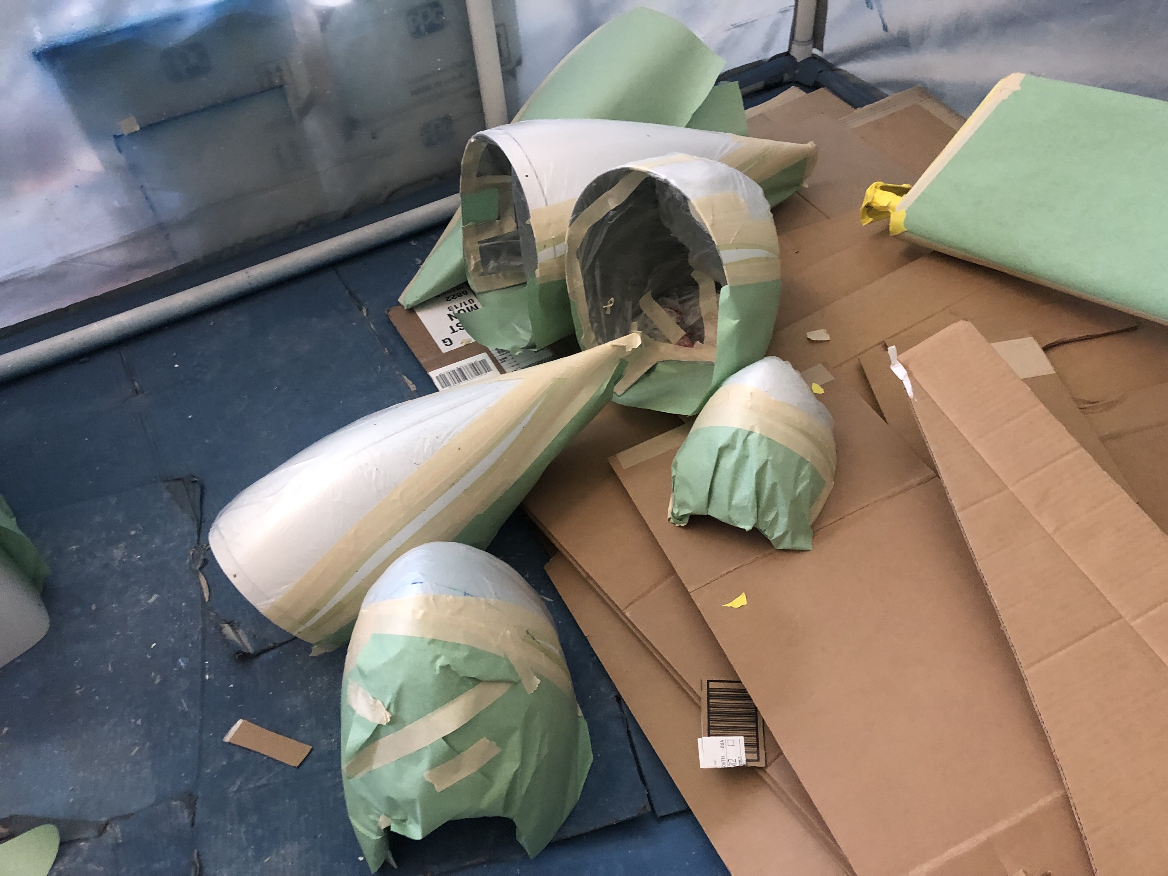
After masking and preparation was complete the blue and turquoise paint was applied to the wings, empennage, cowl and wheel pants.
Time: 6 hours.
Masking was done for the blue areas and for the turquoise stripes on the empennage, cowl, wings and wheel pants.
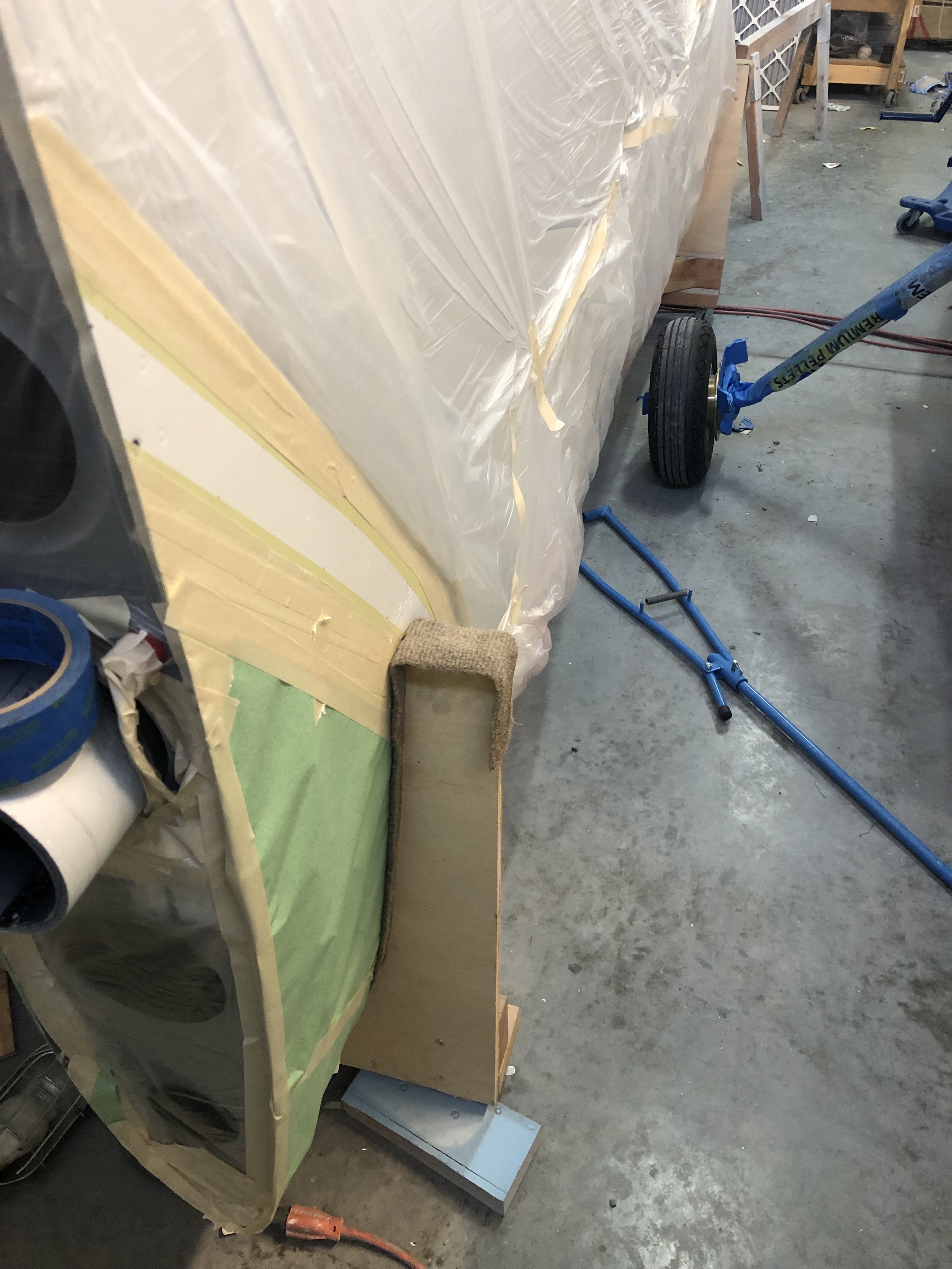
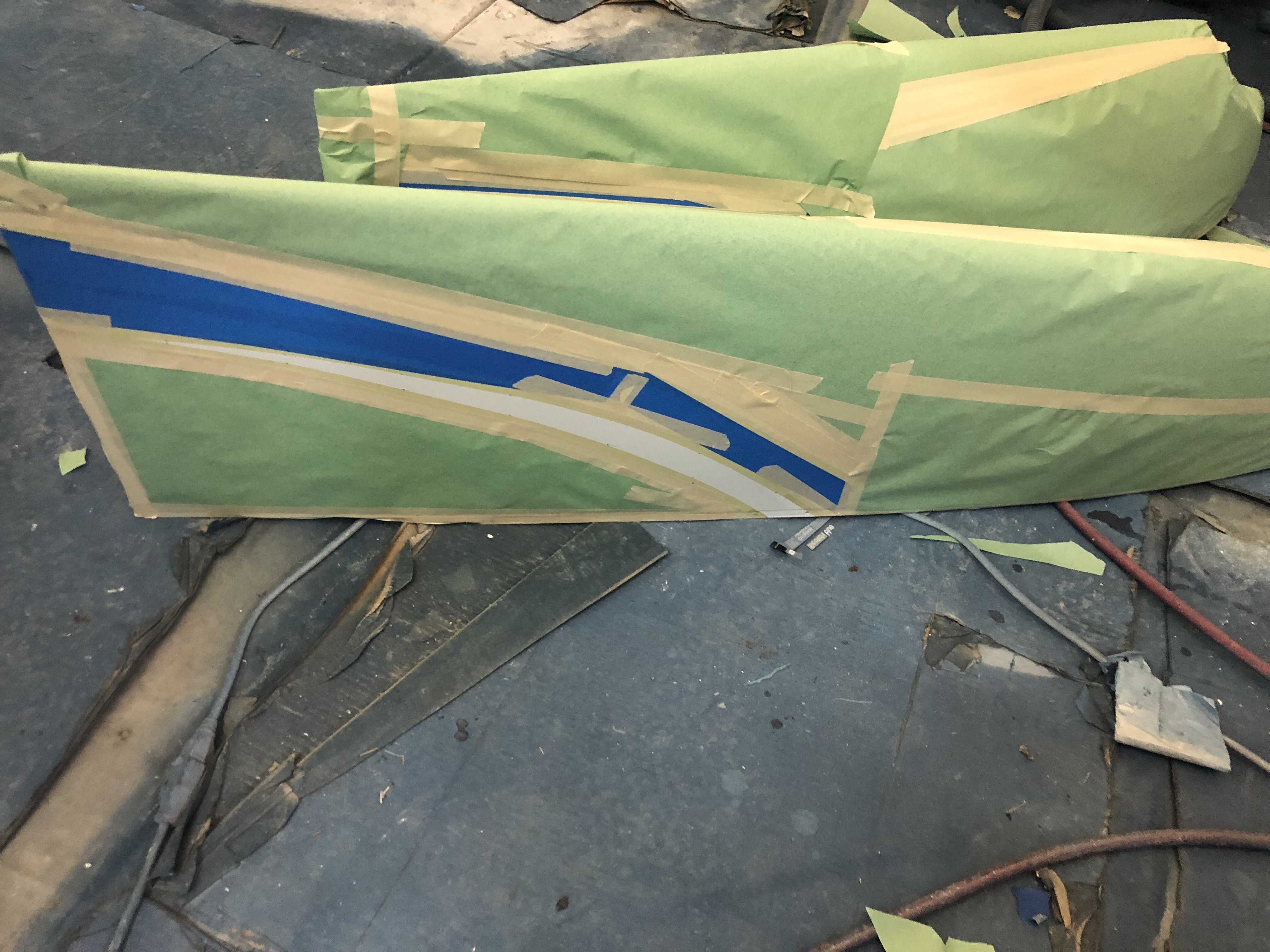

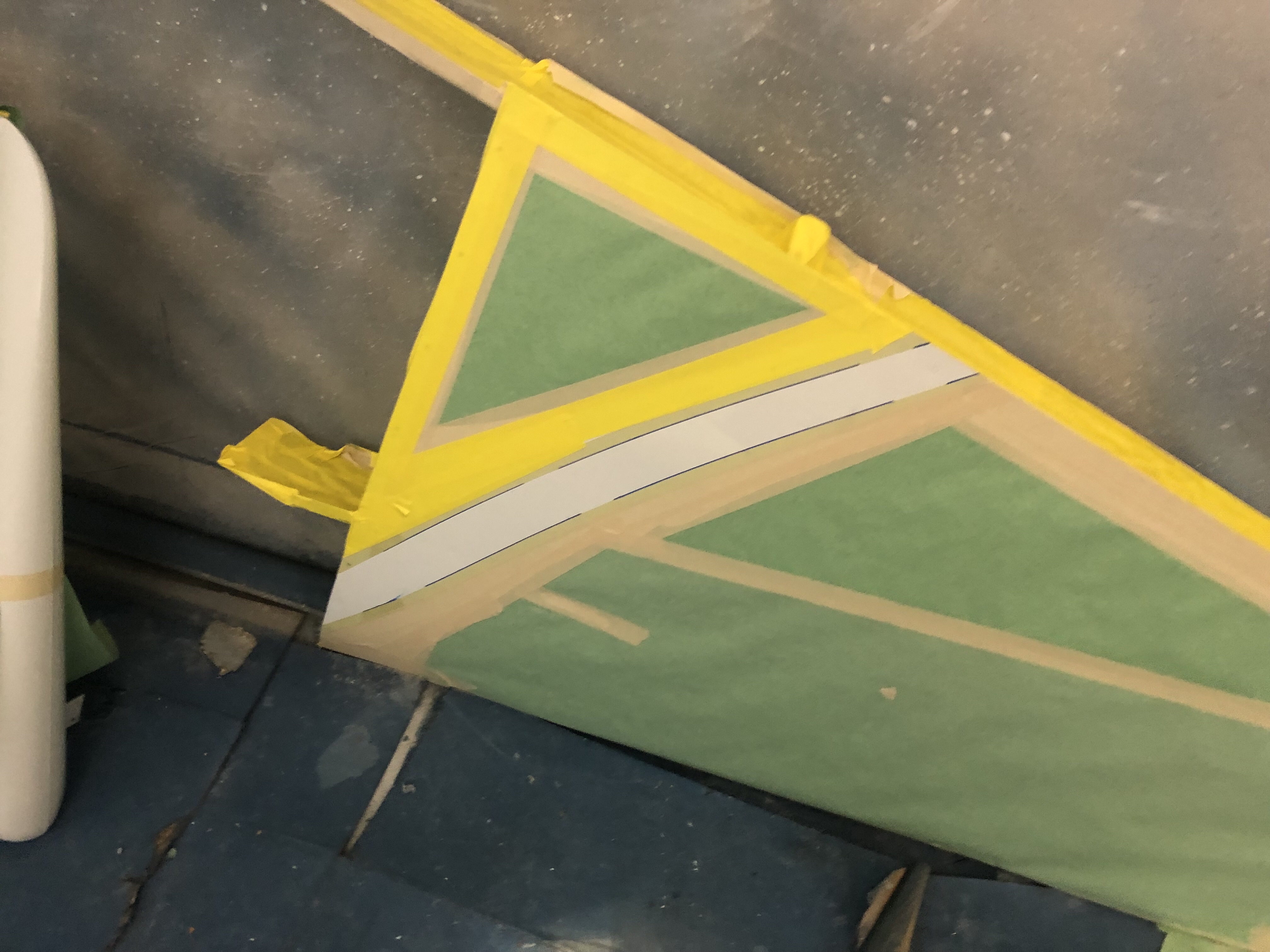
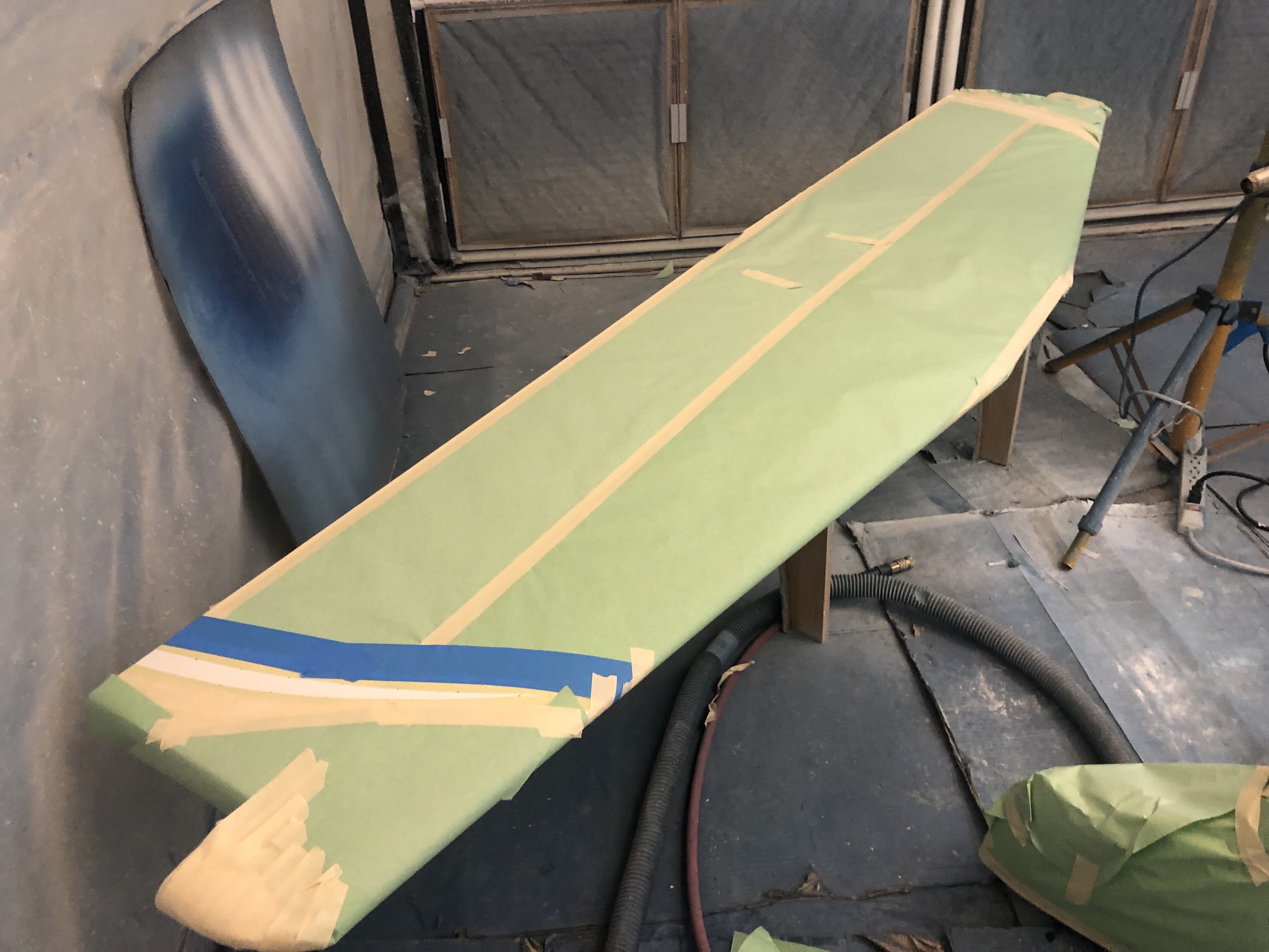
Time: 8 hours.
After preparation the turquoise paint stripes were applied to the fuselage.
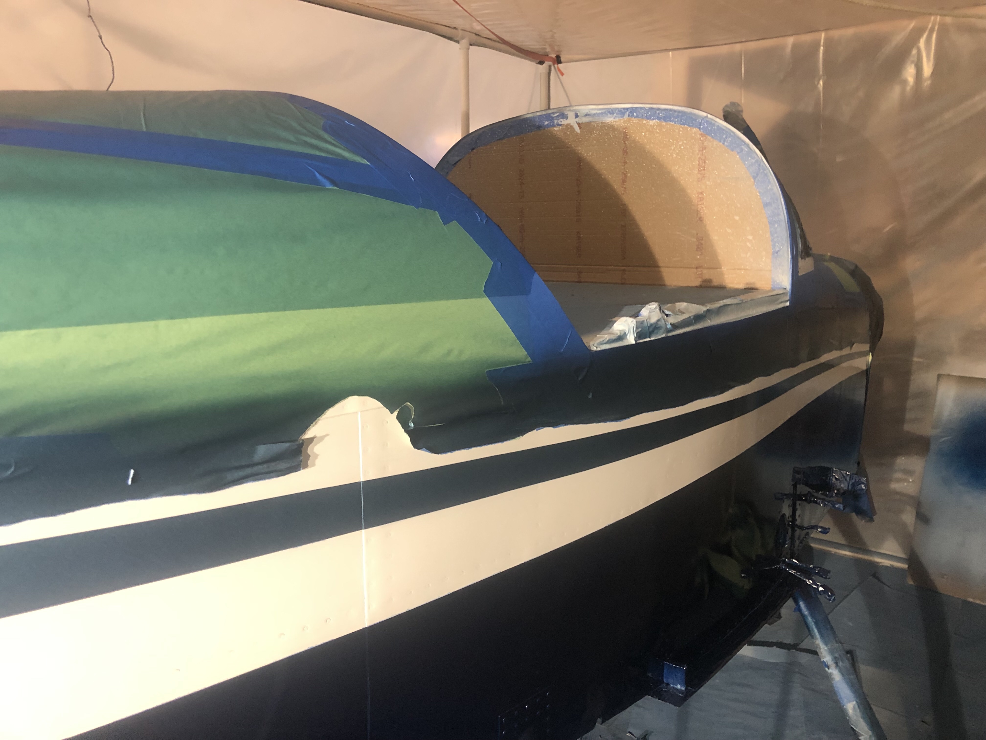
Time: 6 hours.
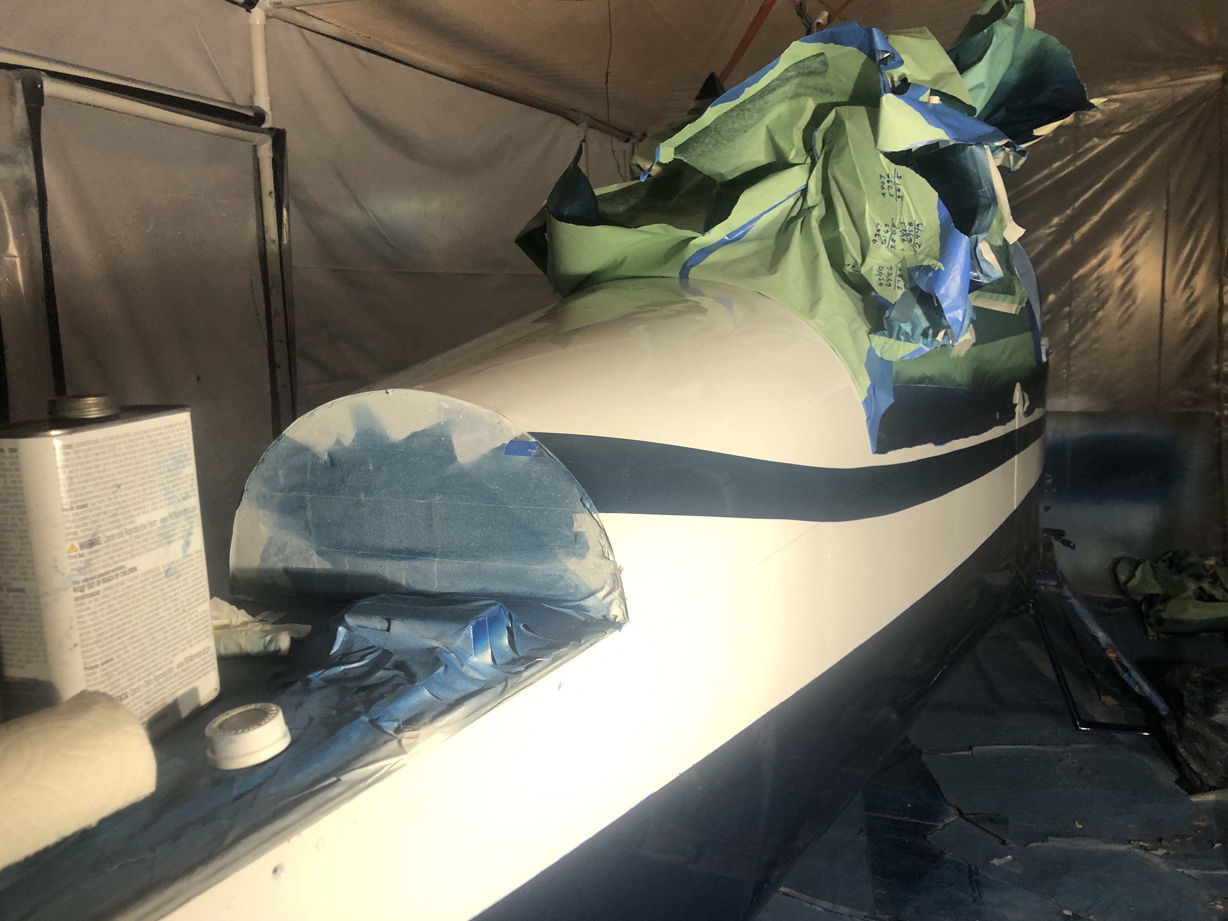
After preparation the dark blue paint was applied to the empennage, fuselage, wings, cowl and wheel pants.
Time: 8 hours.
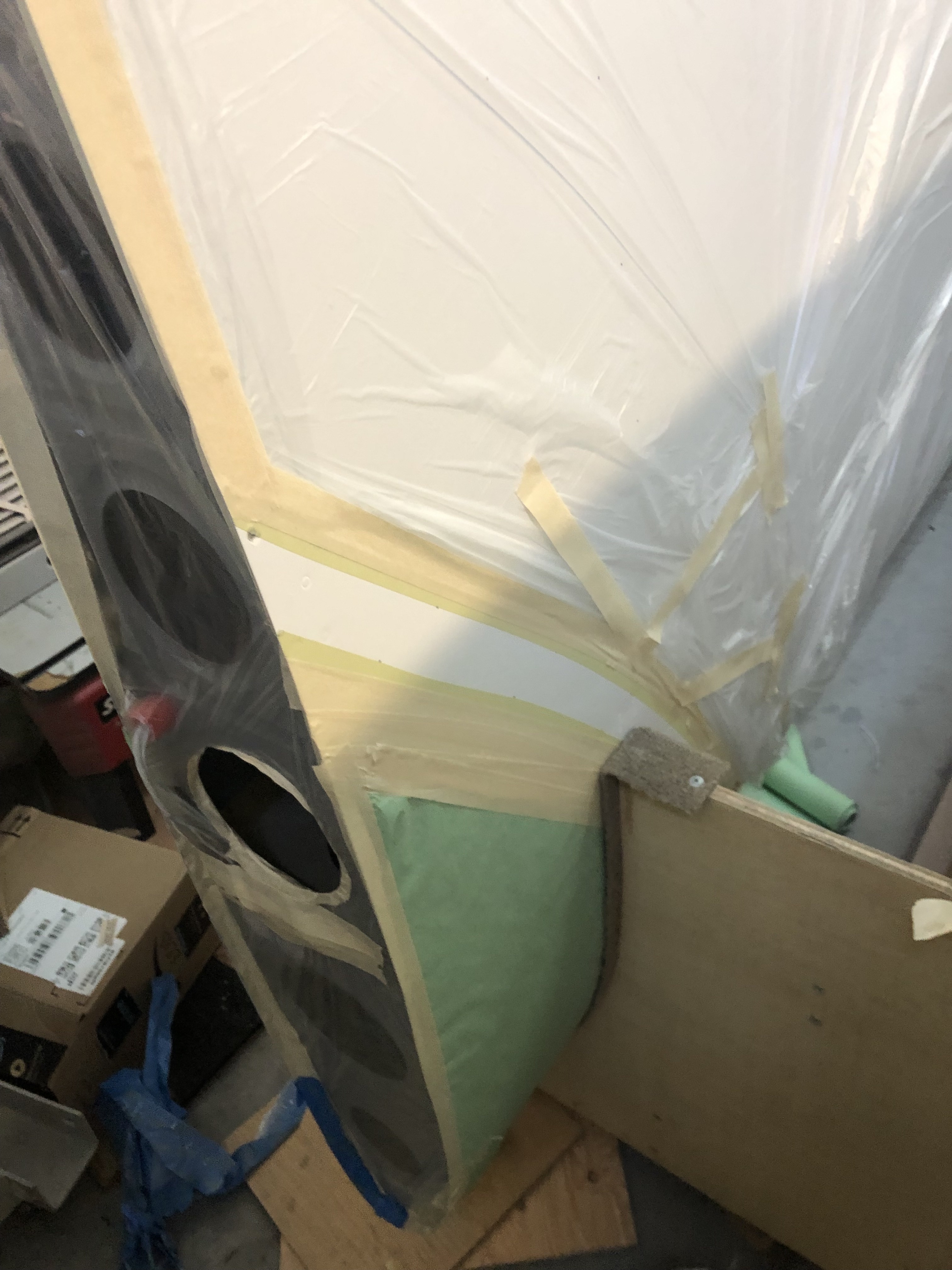
I marked the border between white and blue paint by marking the vertical position every 10 inches on the fuselage, every 4 inches on the wings and empennage and every 2 inches on the wheel pants. These marks were connected using a stiff wire to create a smooth curve with an erasable marking pen. This line was then used to locate the 1/2” flexible vinyl masking tape.
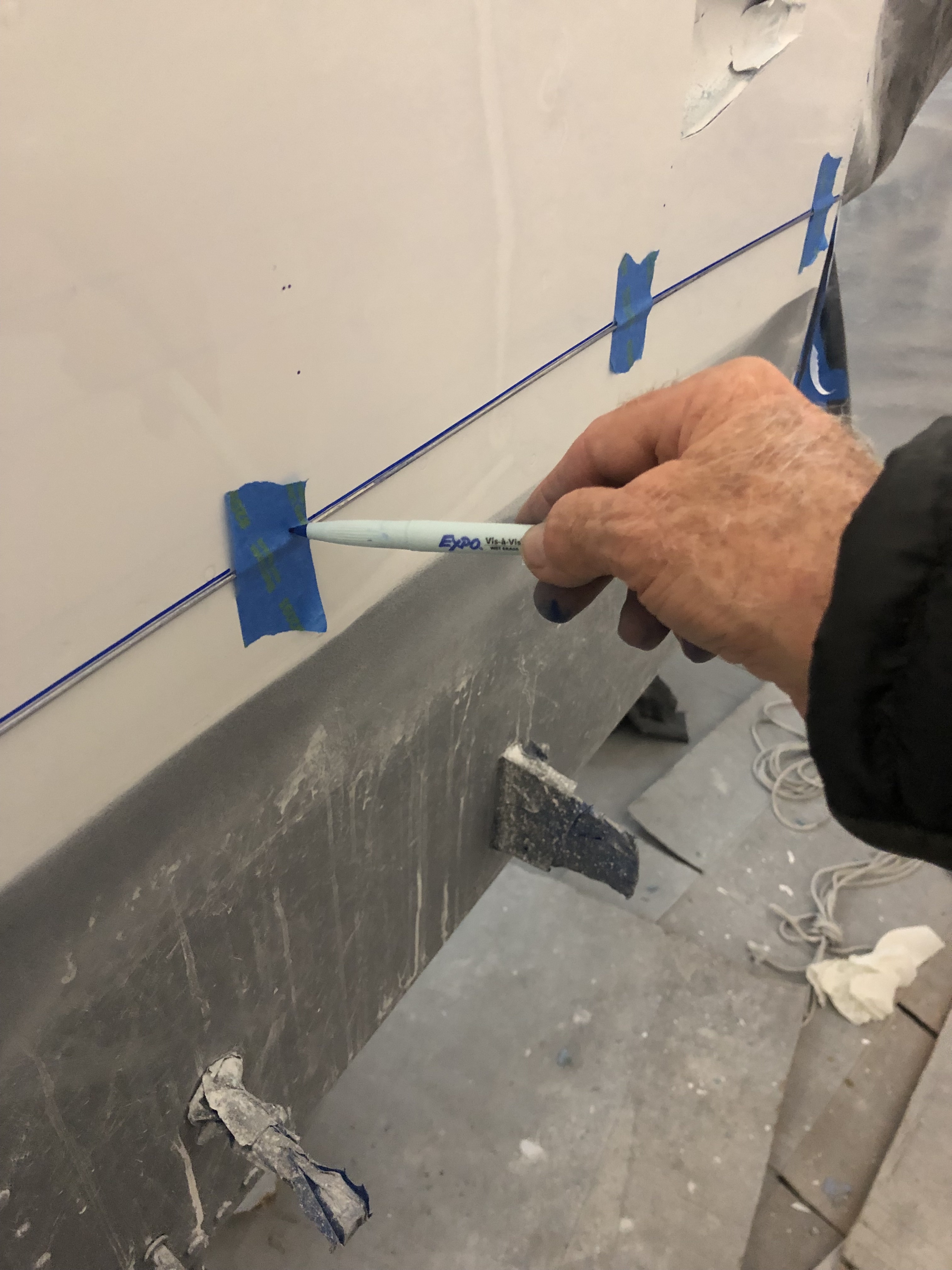
Time: 6 hours.
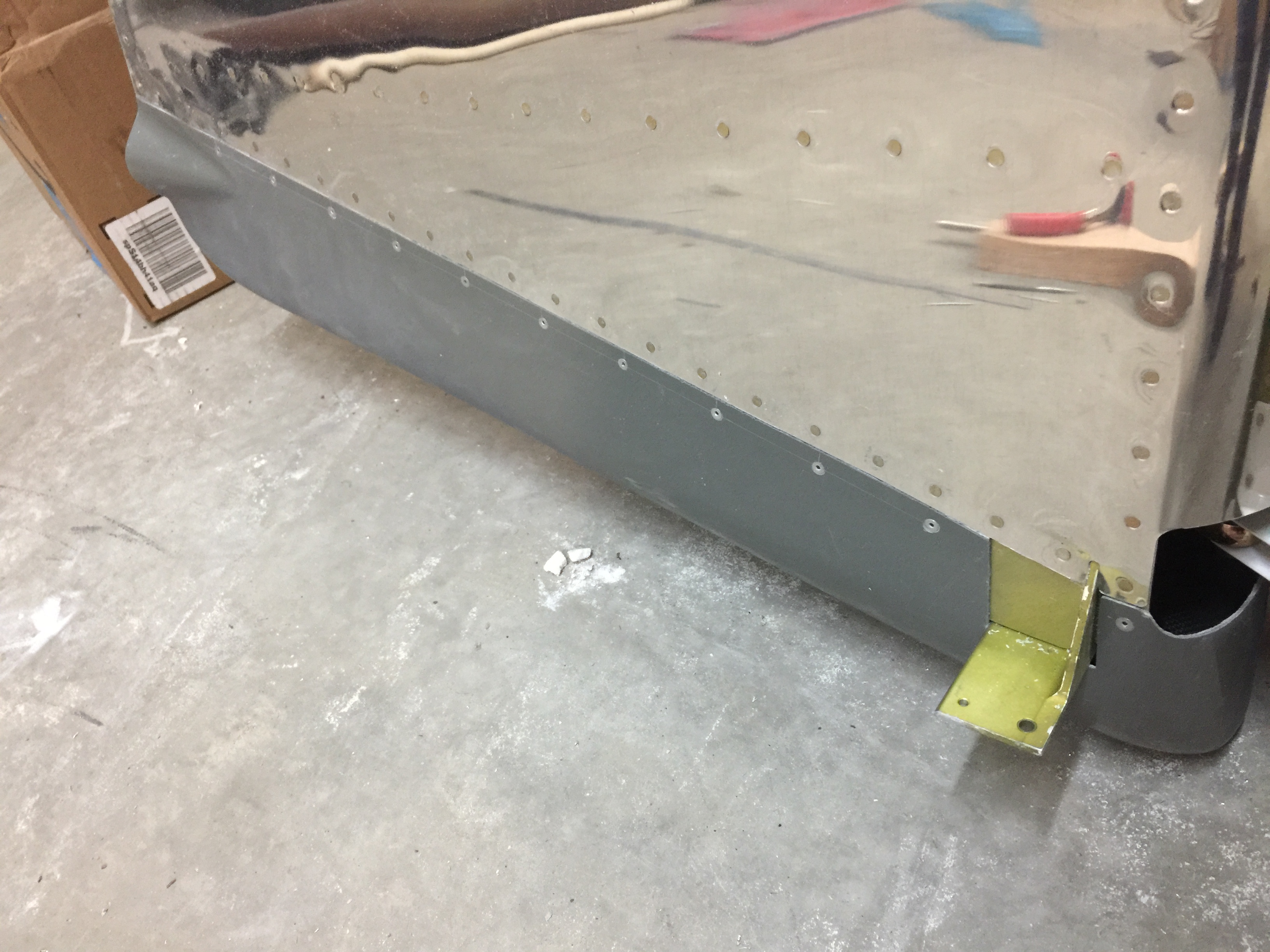
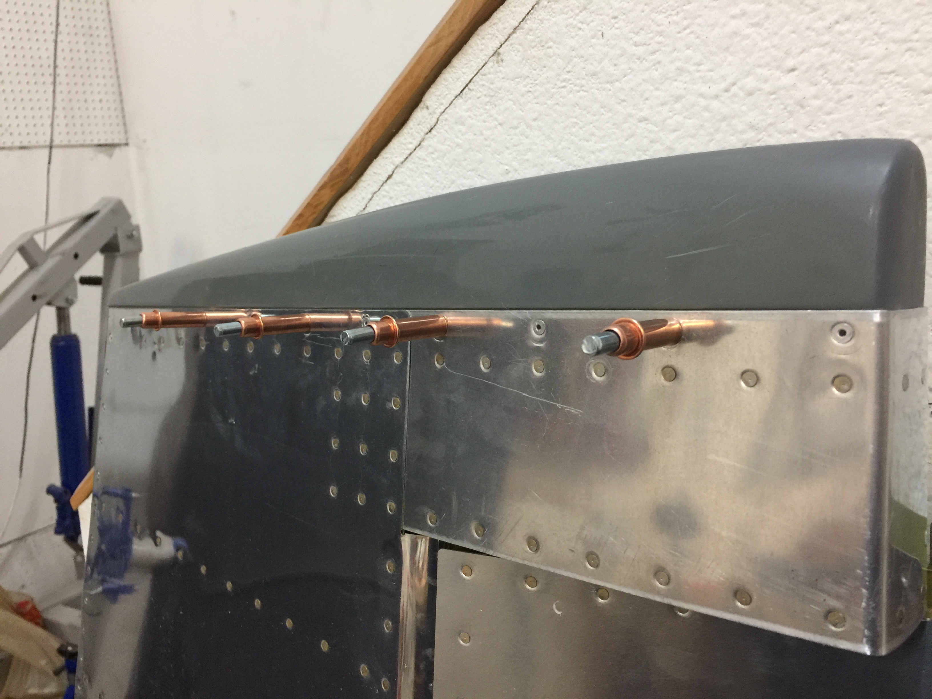
The empennage fairing was installed according to the details found on drawing 44.
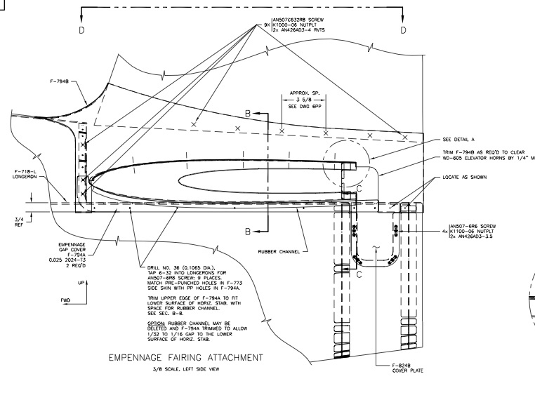
The fiberglass fairing was fitted to the empennage surfaces by filing and the application of heat. Nut plates were installed in the indicated locations.

The rubber channel seal was adapted and installed.
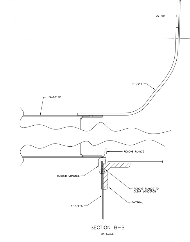
Time: 12 hours.
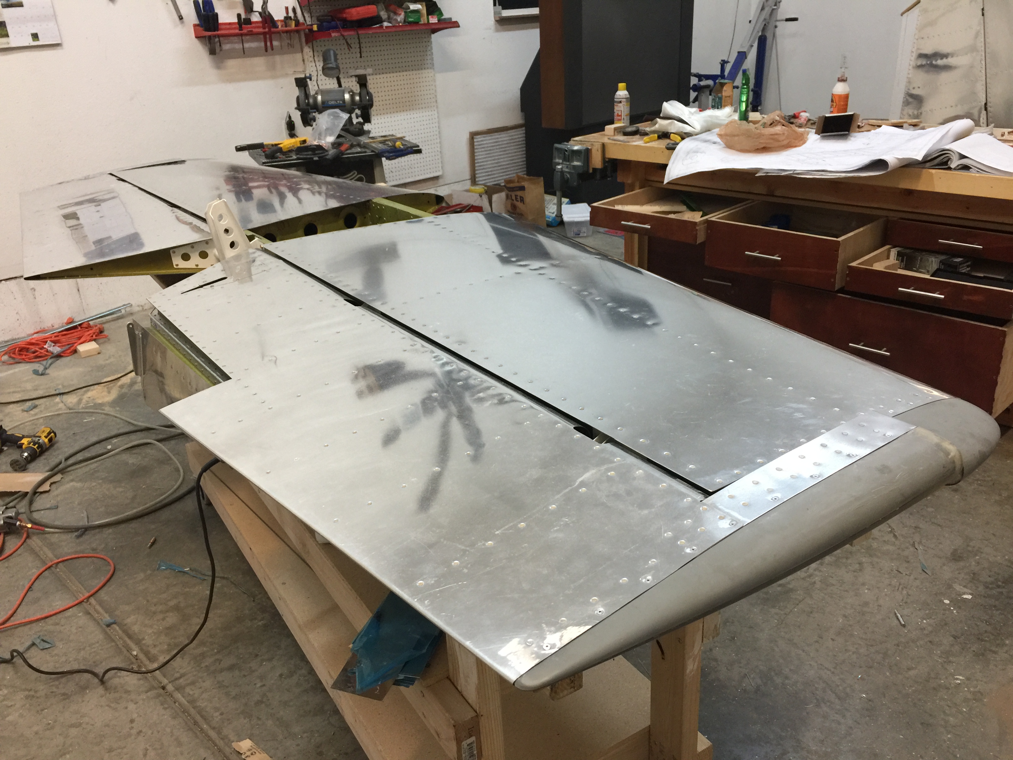
The elevators were fitted to the horizontal stabilizer during construction, but the lower bolt hole in the elevator horns (to which the pushrod attaches) had not been drilled yet. These holes were best drilled with the elevators mounted to the stabilizer. This hole had to be be exactly perpendicular to the horns. If it wasn’t, when the bolt installing the pushrod was tightened, one horn would be pulled forward and the other aft, mis-aligning the counterbalance arms.
I clamped the horizontal stabilizer to the bench with the hinges hanging over the edge and mounted the elevators on the stabilizer. I then aligned the elevator counterweight arms to the stabilizer tips and clamped them so they would not move. I then measured the distance between the inside faces of the elevator horns.
The horns are individually welded and seldom does one side match the other exactly. Usually the mis-match is slight. I determined which horn was aft, then removed that elevator and drilled a #30 pilot hole in the horn at the dimensions shown on DWG 27A, Side View.
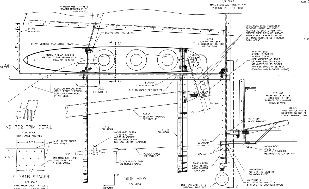
I made a hard wood block that fit exactly between the inside faces of the horns. The exact size of the block was unimportant, but the two outside faces had to be parallel. I used a drill press to make a #30 hole perpendicular to the faces of the block.
Then the elevator was remounted and the counterweight arm was fixed to the stabilizer. The block was clamped between the horns and the hole in the block was aligned with the hole in the one horn. Then the block was used as a guide to drill the other horn. Once pilot holes had been drilled in both horns, they were enlarged to full size. This could be done one horn at a time.
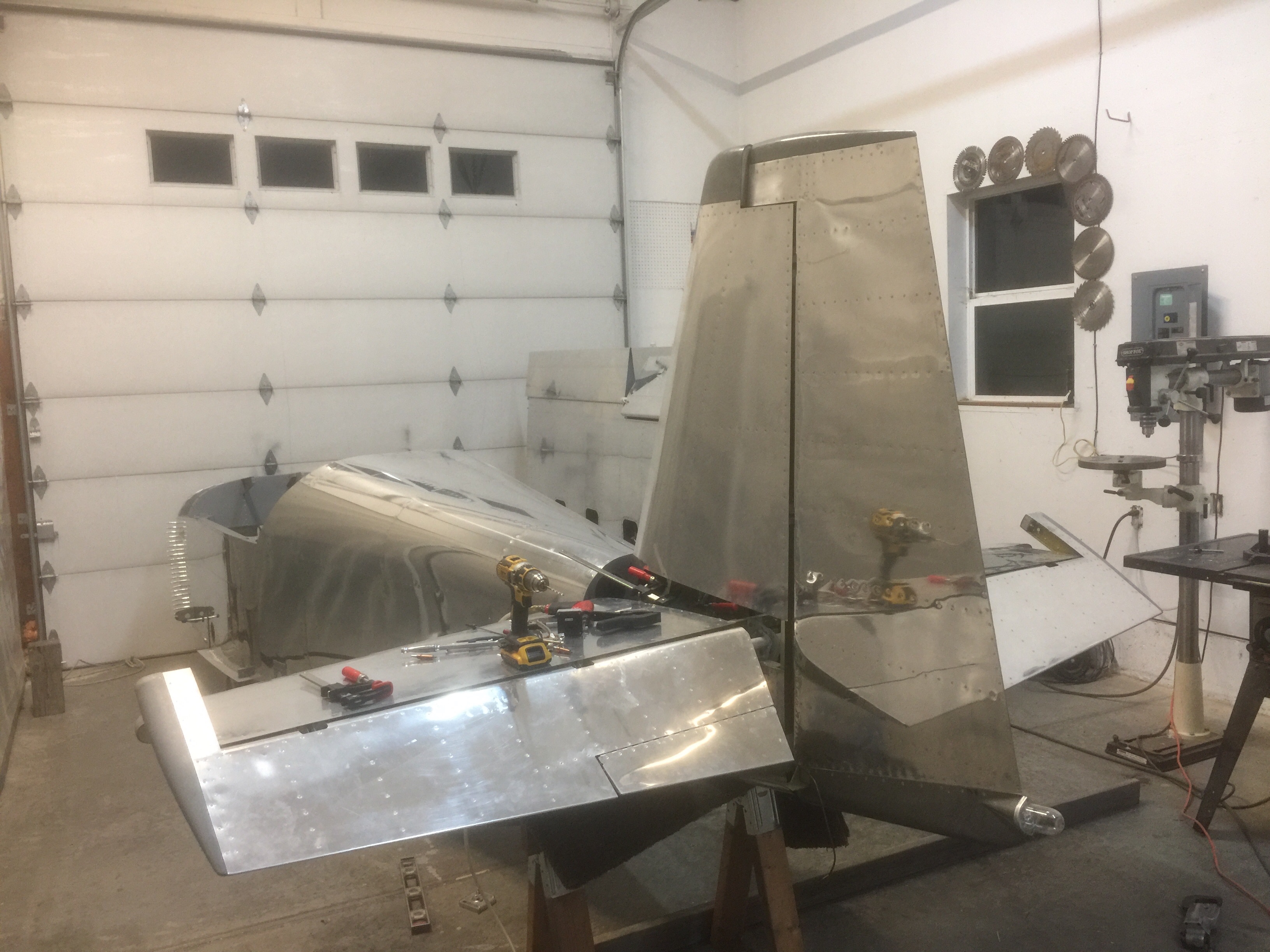
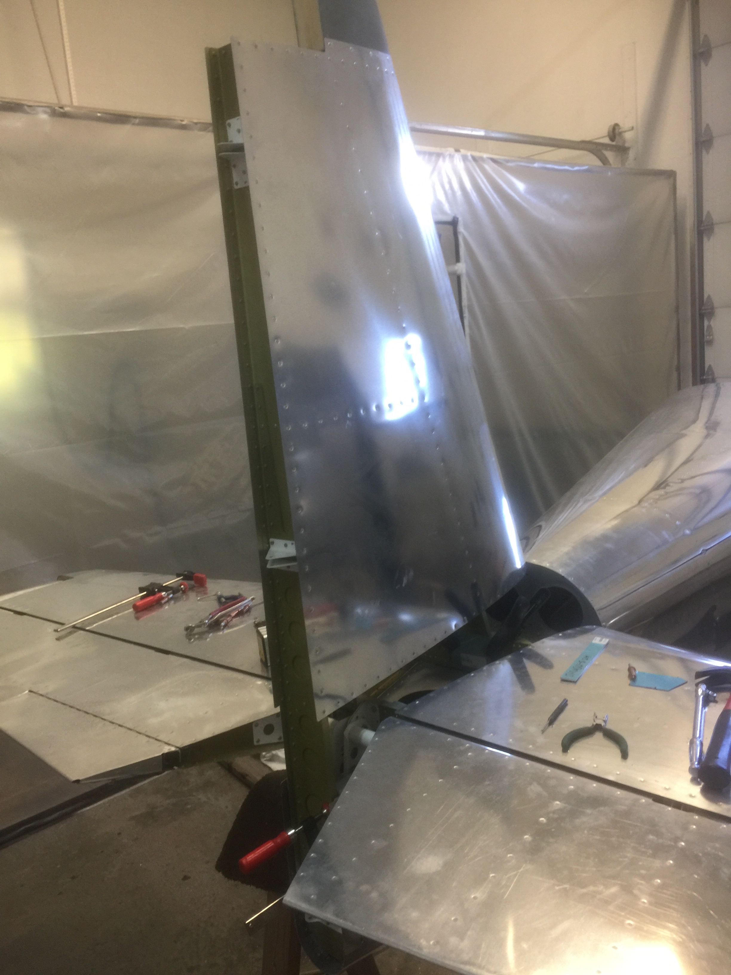
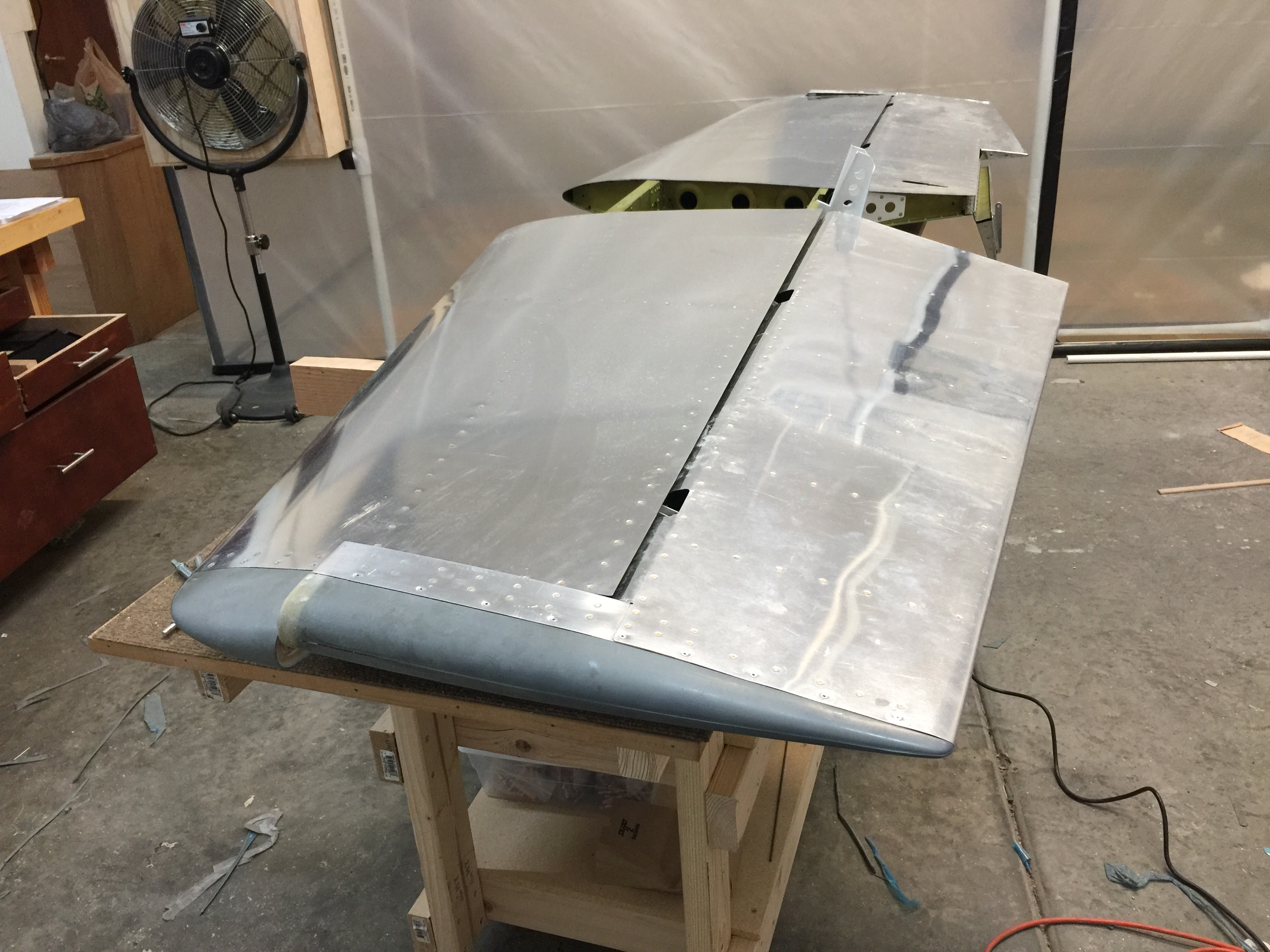
The horizontal stabilizer was clamped to the aft fuselage. The stabilizer needed to be perpendicular to the longitudinal centerline of the fuselage. I pre-positioned the inboard edges of the skins parallel to the longerons. This was checked by running a tape measure from the outboard end of the stab to the corner of the firewall. Using similar points on both sides of the airplane and the stabilizer was adjusted until the measurements are equal.
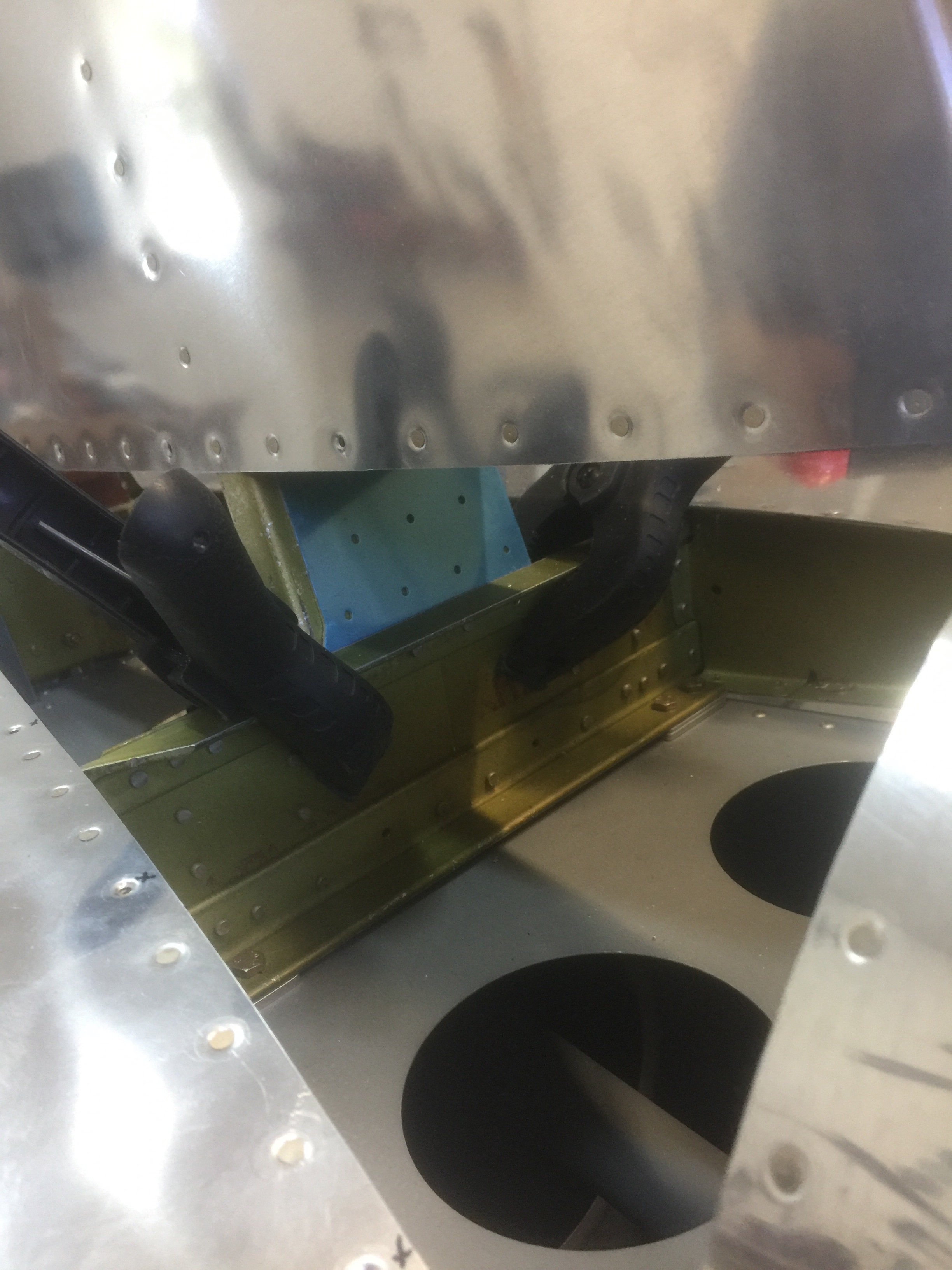
Once the stabilizer was located, it was time to drill the holes though the HS-714 attach angle on the forward spar.
The outboard holes had to go through the fuselage longerons, the F-710C spacer and F-710B angle (see Detail B, DWG 27A). These parts were underneath the F-714 deck and invisible. I took careful measurements and located these bolts as accurately as possible. I remembered that the vertical leg of the longeron is 1/8″ thick and the bolt had to center in the available 5/8” of the horizontal leg.
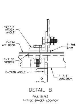
When the HS-714 angle had been drilled, I made the F-798 shims, slipped them between the deck and the angle and used the holes as guides to drill the shims.
I then temporarily bolted the forward spar and shims to the fuselage. Using a 3/16″ spacer I slid it between the rear spar of the stabilizer and the aft deck. This set the spacing necessary to obtain the desired 0 degree incidence. I checked this by measuring from the deck to the tooling holes in the inboard stabilizer ribs. The measurements were be the same, fore and aft.
When the stabilizer had been located, I drilled the bolt holes though the F-711C bars and the rear spar of the stabilizer.
Time: 12 hours.
The lower rudder tip required quite a bit of trimming but the trim line was marked on the fiberglass and the installation was uneventful.
The upper tip was also installed without incident the same as the matching vertical stabilizer tip.
With this the work on the empennage is finished!
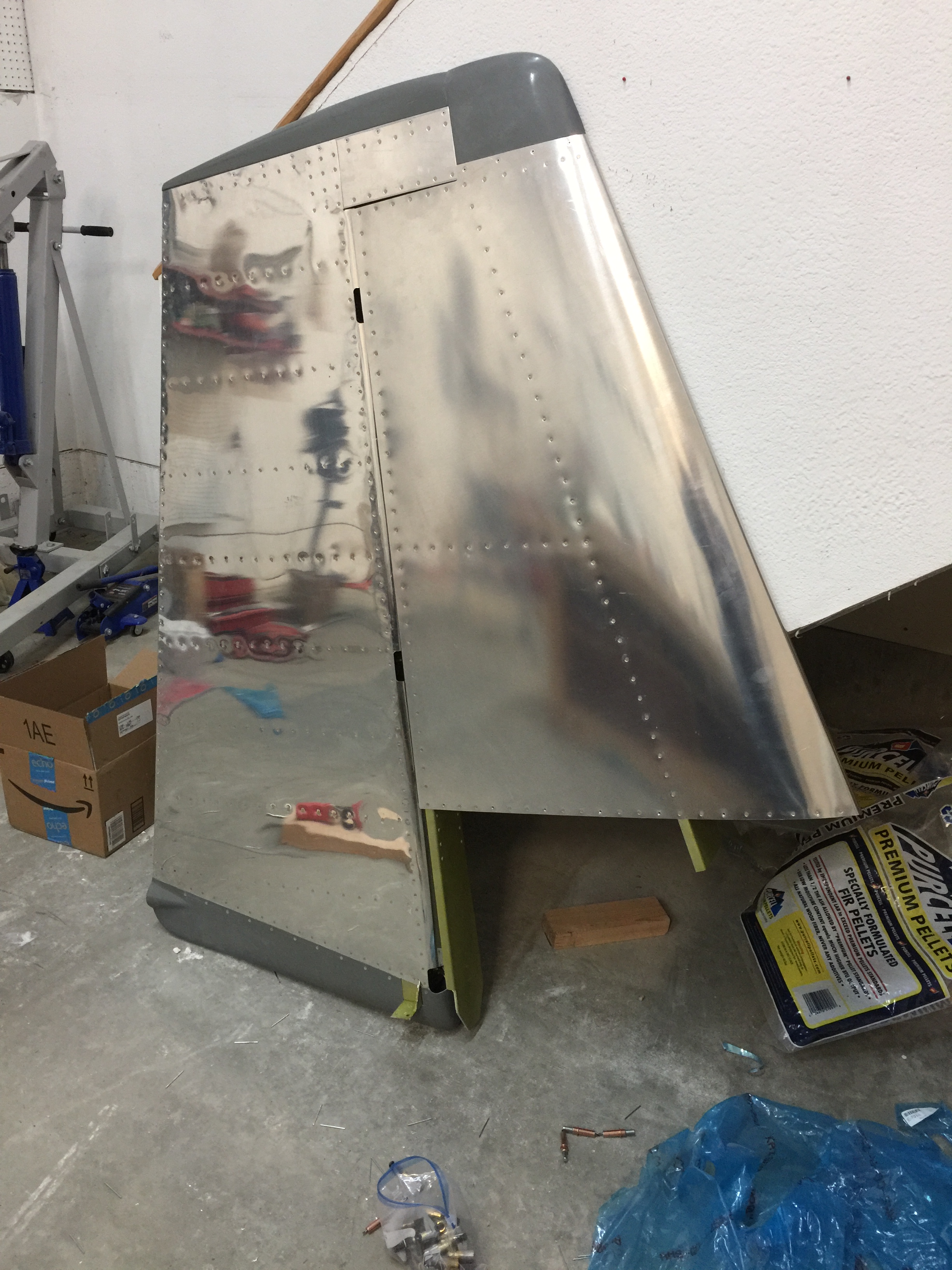
Time: 8 hours
