I deburred all of the parts of the fuselage and countersank the holes in the longerons in preparation for final assembly.


Time: 6 hours

I deburred all of the parts of the fuselage and countersank the holes in the longerons in preparation for final assembly.
Time: 6 hours
I disassembled the entire fuselage in preparation for deburring, priming and final assembly.
Time: 3 hours.
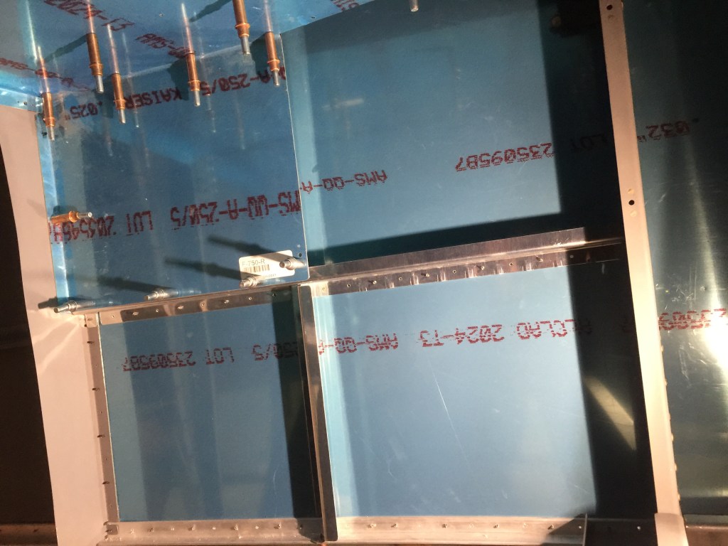
DWGs 25 and 29 show that the inside of the baggage area sidewall is partially covered with two panels. The aft is permanent, but the forward panel must be removable to give access to the flap mechanism. These panels are supported by two ribs, one vertical, one horizontal. I fit the F-724 vertical rib by clecoing it to the F-770 side skin. I then installed the nutplates on the F-722 horizontal ribs and drilled and clecoed them to the side skins. I clecoed the F-750 aft baggage side covers to the F-722 and F-724 ribs, adjusted the top and bottom flanges of F-724 to the longeron and the F-623 rib, and drilled them.
I did additional fitting of the gear mounts and fitted the gear to the mounts.
I also reinforced the armrests with J profiles.
Time: 8 hours.
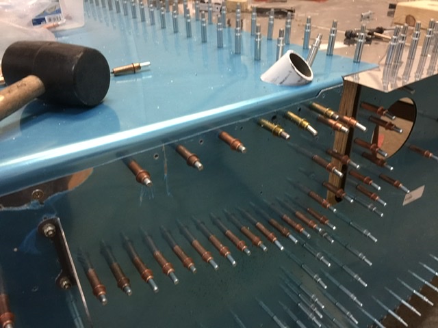
I clecoed the F-772 forward bottom skin back on the fuselage. I then drew centerlines on the back of the F-772B-R&L Floor Stiffeners. This made it possible to watch for the centerlines while shifting the stiffeners to fit them to the F-772 skin correctly.
When the floor stiffeners were located, I drilled them to the skin, firewall, and center section bulkhead. The center floor stiffeners were also drilled to the bottom of the F-783B-L&R Cover Support Ribs and F-601J angles on the firewall. I made sure the stiffener was firmly against the floor and bulkheads before using an angle drill to make these holes.

I also installed the rudder pedal/brake assembly with three sets of mounting holes.
Time: 5 hours.
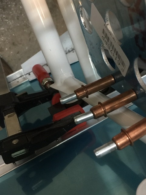
I drilled F-772 Forward Bottom Skin to final sizes to accommodate the bolts fastening the skin to the firewall braces.

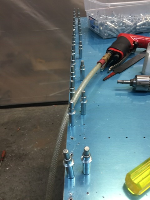
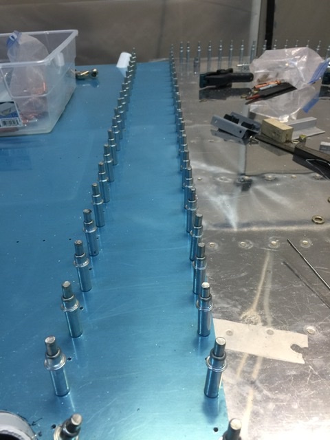
I had to do quite a bit of fitting to let the strut fittings come through the bottom skin correctly.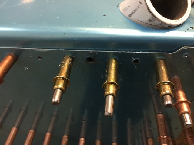
Time: 8 hours.
DWG 37 showed details of installing the rudder and brake pedal assemblies. I chose to do this while access is still available.
I assembled the F-6117-L&R Brake Pedals.
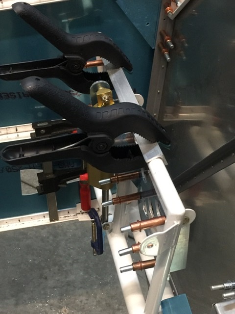
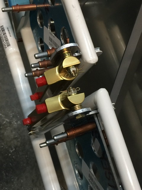
The Wd-655R&L Rudder Pedal Assemblies were assembled with the brake and master cylinders bolted on as shown on the Exploded View of DWG 37. The F-6116 Side Bearing Blocks were slipped over the end of the rudder pedal tubes and the assemblies were dropped into the fuselage from above. Note that the right side pedal assembly was forward of the left side.
The exact fore-and-aft location of the F-6116 bearing blocks was left to me to decide. The recommendation is to drill several attachment hole patterns so the location can be changed easily if it becomes necessary. I drilled 3 separate locations and remembered to maintain at least two hole diameters between the edges of the holes.
I bolted the rudder pedal assemblies to the longerons with bolts through the side bearing blocks and trimmed the F-6118 Rudder Pedal Brace as shown. The extra length of the notch in the bottom flange would accommodate the F601K Firewall Recess. I fit the F-6115 Center Bearing Block around the Wd-655 rudder pedal tubes and bolted it to the brace, clamped the brace against F-601 upright firewall stiffener and drilled. It was easier for me to drill from the inboard face of the F-601, reaching through the open hole for the F-601K recess. I planned the holes so the rivets didn’t interfere with the rivets that attach the recess coming through the other leg of F-601N.
I finally removed and stored the rudder pedal/brake pedal assemblies.
Time: 8 hours.
I removed the F-796B and clecoed the F-796C & D spacers to the F-796B angle. I aligned the part edges and match-drilled all the holes through F-796C & D using the holes in F-796B as guides.
I then clecoed the angle and spacers back in the fuselage. I was able to clean up small hole misalignments by running a #40 drill through the part stack-up. Large hole misalignment could have been cleaned-up by running a #30 drill through the stack-up and installing 1/8 inch rivets instead of 3/32 inch rivets. I removed the parts and set them aside for later installation.
Time : 3 hours.
I made the F-796C & D Spacers as shown on DWG 38. I then drilled the top 3/32” hole in the spacers at the dimensions shown, but left the other holes undrilled for the time being.
I made the F-796B reinforcement angle (DWG 38) and drilled only the top hole. I then drilled the 3/16” hole to #30 for now.
I studied drawing 38, Detail F to better understand the fit of the spacers and angle with the bulkhead flange and longerons.
I put a centerline on the outboard face of the F-796B angle and clecoed it on the inside of the longerons using the upper pilot hole drilled in the angle. When the centerline on the angle was visible through the lowest hole in the side skin, I drilled and clecoed it to the fuselage. I match-drilled the remaining holes through the angle using the holes in the skin as guides. I drilled as straight as possible so as to minimize any hole position error due to the gap between the skin and angle.
Time: 4 hours.
I adjusted the flanges of the F-902-L&R Forward Bulkheads until the web was perpendicular to the aircraft centerline. I checked by using a straightedge between the two bulkhead webs to see that they were parallel. I straightened the bulkheads as necessary with flutes between the rivet holes. Then I opened the hole for the rudder cable to 5/8”.
I then riveted the nutplates to the aft side of the F-902 bulkhead. These would later hold clamps securing the fuel vent line.
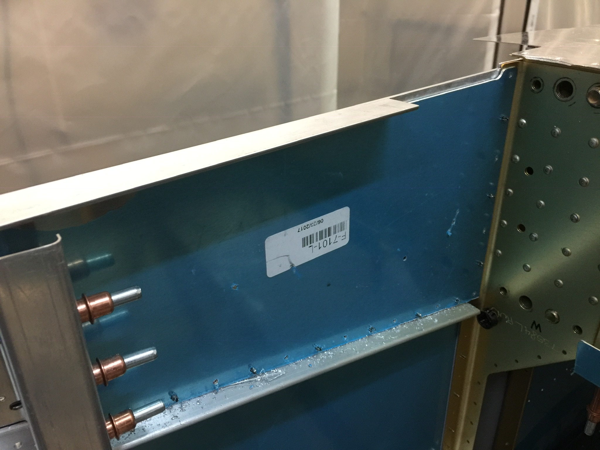
I clecoed the F-7101 Gear Attach Web to the F-704 bulkhead. This rested the web of the F-902 against the forward flange of the F-7101. I made some necessary small adjustments and then drilled and clecoed the F-902 to the F-7101 and the skin.
I adjusted the top and bottom tabs of F-902 as necessary to fit the longerons, and then drilled and clecoed.
Time: 2 hours.
Before drilling holes for the rivets that join the lower longerons and auxiliary longerons to the Wd-603 brackets, the F-684 gussets had to be fitted. These required some careful edge filing to fit really well, but this was an important juncture, so I made sure all the parts fit before riveting. The forward edge of F-684 needed to be 1/8” aft of the firewall bulkhead and the lower edge needed to align with the lower edge of the F-713 Aux. Longeron. I adjusted the bend angle as necessary to make the gusset lie flat inside the Wd-603 bracket and the vertical firewall angle. See Section K-K’, DWG 23. I clamped the assembly, drilled as shown on Detail A, and clecoed. The holes in the skin acted as guides.
Time: 2 hours.
