I drilled and riveted the Aft Baggage Side Covers to the inside of the fuselage.

Time: 3 hours.
I drilled and riveted the Aft Baggage Side Covers to the inside of the fuselage.
Time: 3 hours.
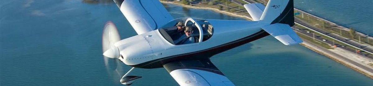
The exterior steps have a mounting flange which must be fitted to the fuselage skin and a tube which is fitted through the longitudinal ribs on the fuselage floor. A block of plastic is used to anchor the end of the tube to the inner rib.

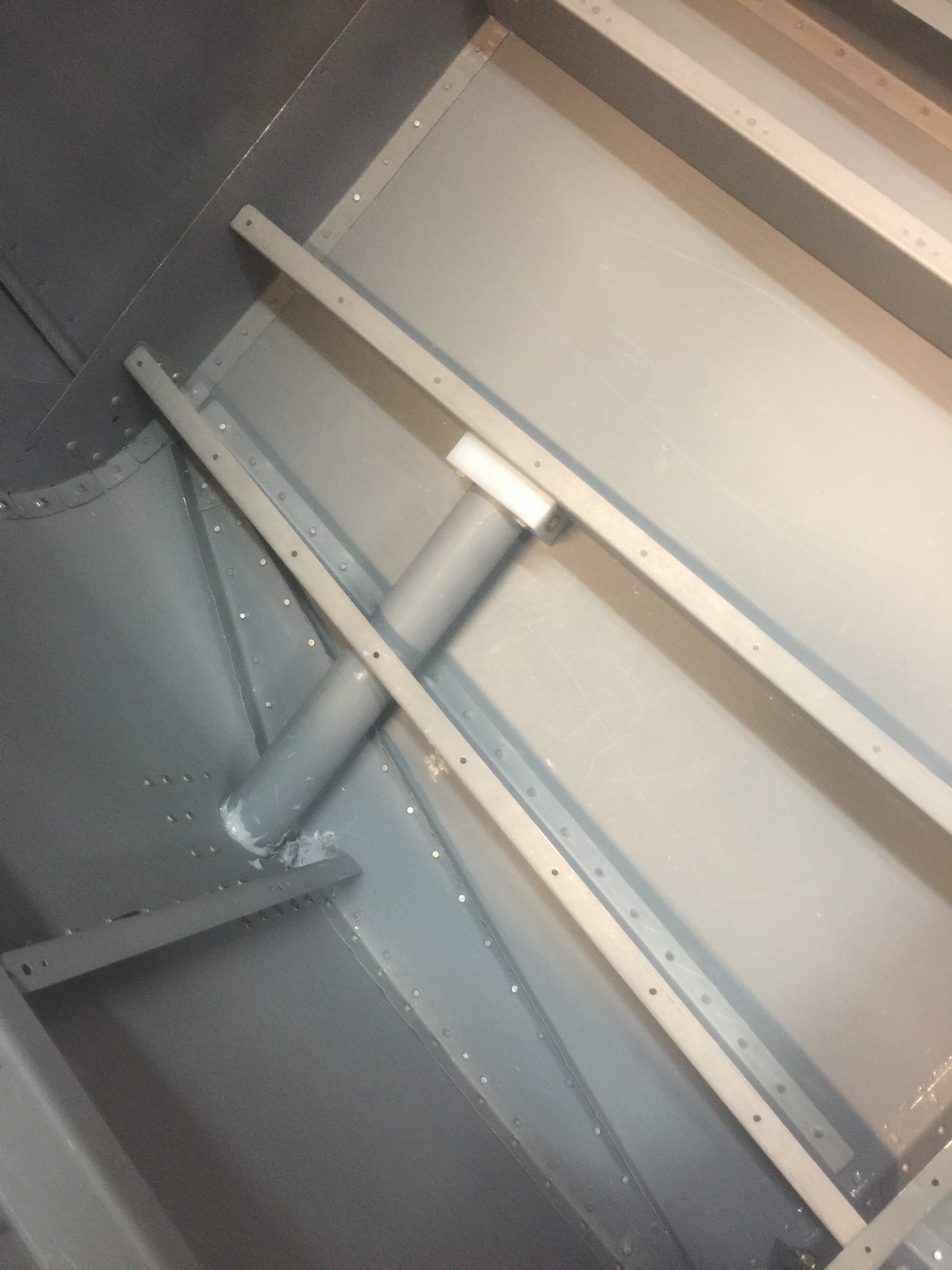
Several iterations of bending and fitting were required to complete the installation.
Time: 6 hours
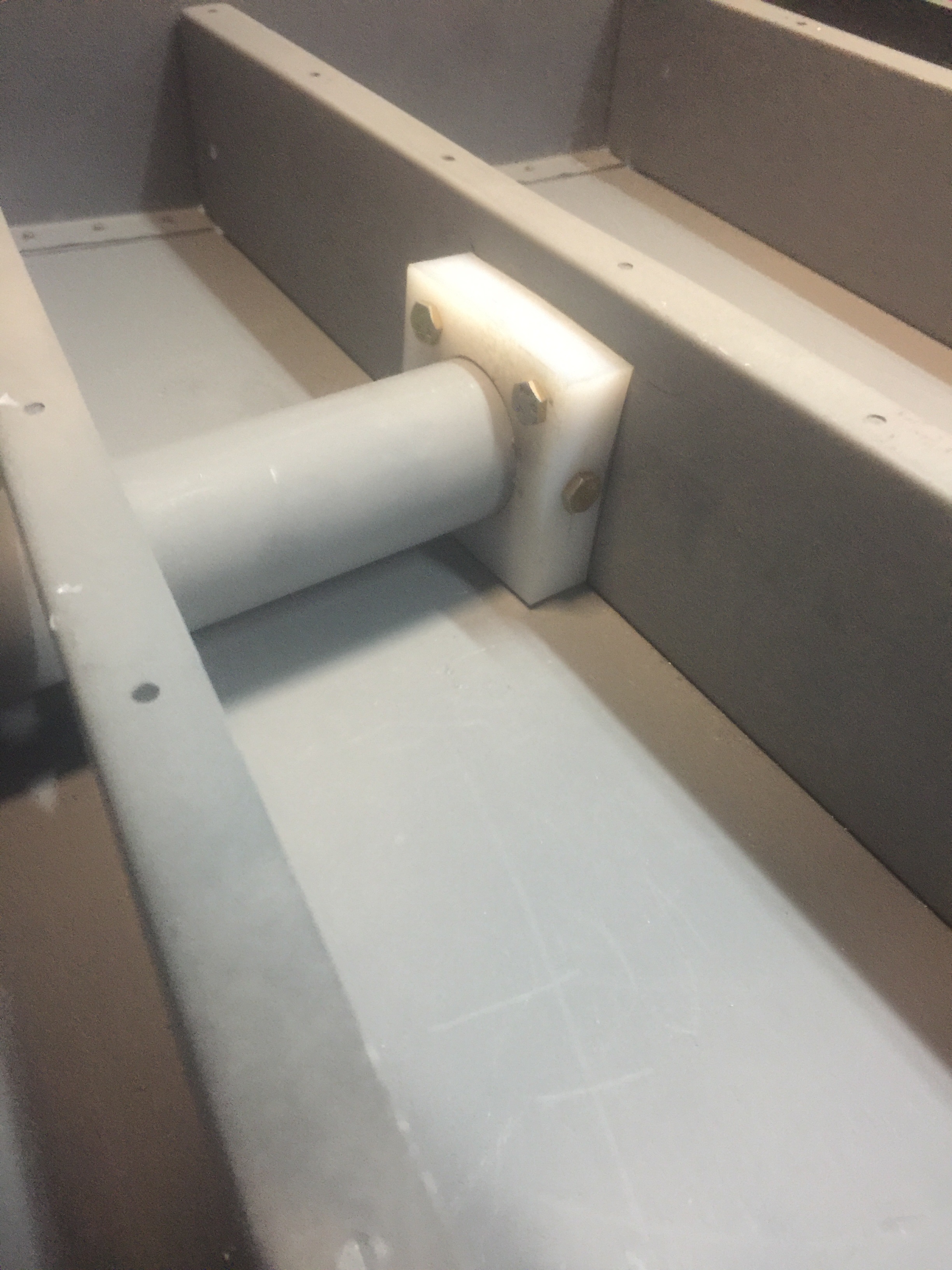
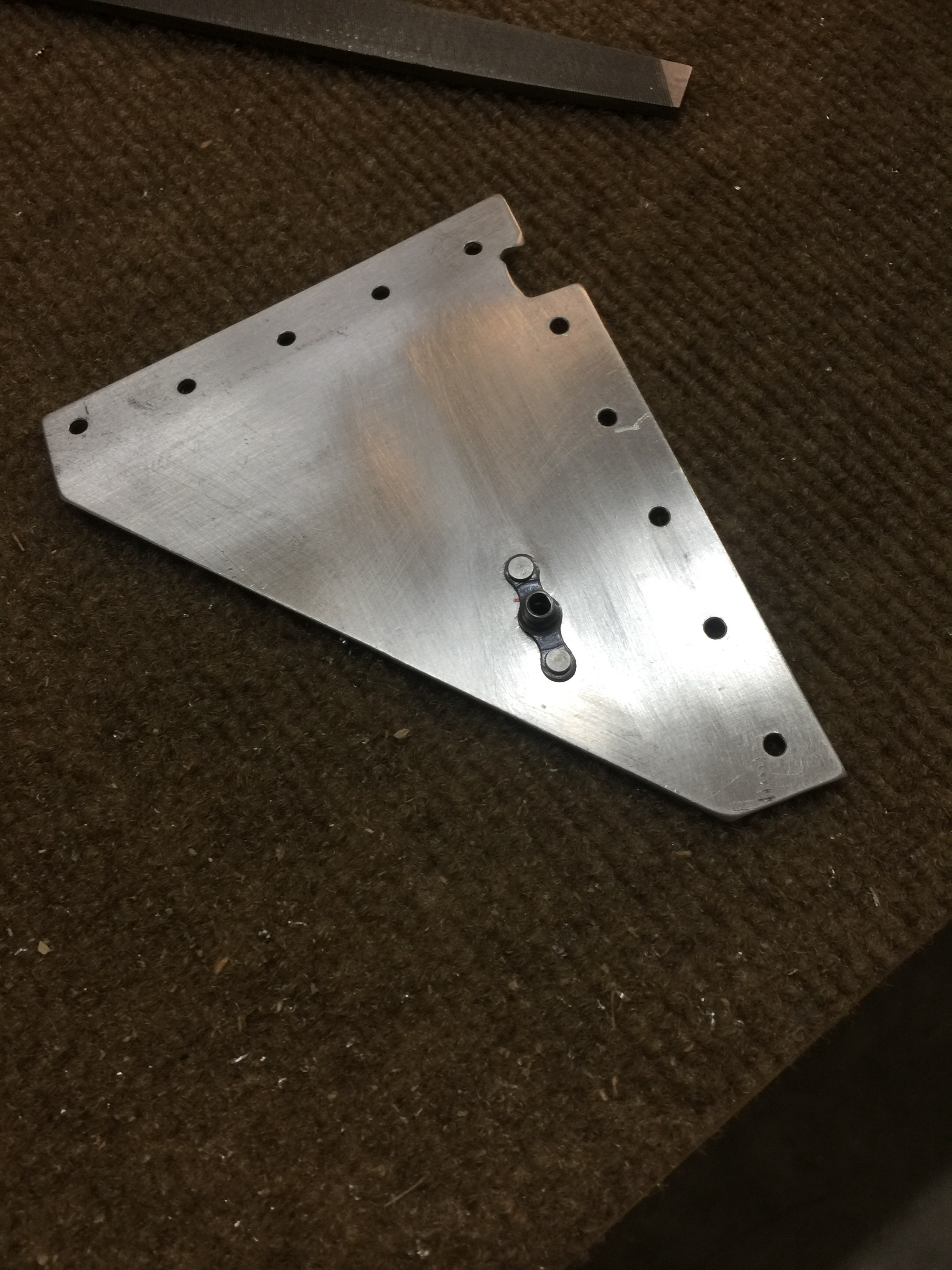
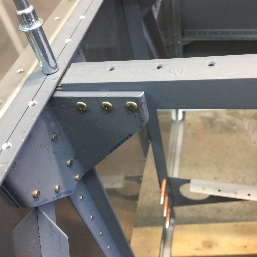
The F-656-L&R gusset plates tie the F-706 and F-707 bulkheads to the main longerons. I clamped the gussets to the longeron, clecoed the gussets to the bulkhead and used the pre-punched holes to drill them to both the bulkhead and the longeron.
I decided to wait until later to rivet them.
Time: 2 hours.
I drilled the F-728A vertical channel to the F-706 bulkhead, then removed the channel. I fit, drilled and riveted the F-728B angle to the channel, then re-installed the channel permanently in the fuselage. I needed to use a narrow bucking bar to set the rivets attaching it to the top of the bulkhead. I fabricated the F-635 Bellcrank by riveting the components around the VA-146 flange bearing. I made the tubular F-635C spacers and fit the bellcrank in the fuselage. I square the ends of the spacers and fit them precisely between the area washers on each side of the bellcrank and the support ribs on either side. The bellcrank was centered between the ribs and rotated smoothly, with no side-to-side play.
I then removed the bellcrank, washers and spacers and stored them.
Time: 4 hours.
The RV-7A shoulder harnesses are secured to the aft fuselage longerons by a stainless steel cable which provides a direct load path. I fit and drilled the F-636 shoulder harness anchors as shown on DWG 26, detail D. I did not bolt them in just yet, because they would interfere with riveting the top fuselage skins to the longerons.
Time: 2 hours.
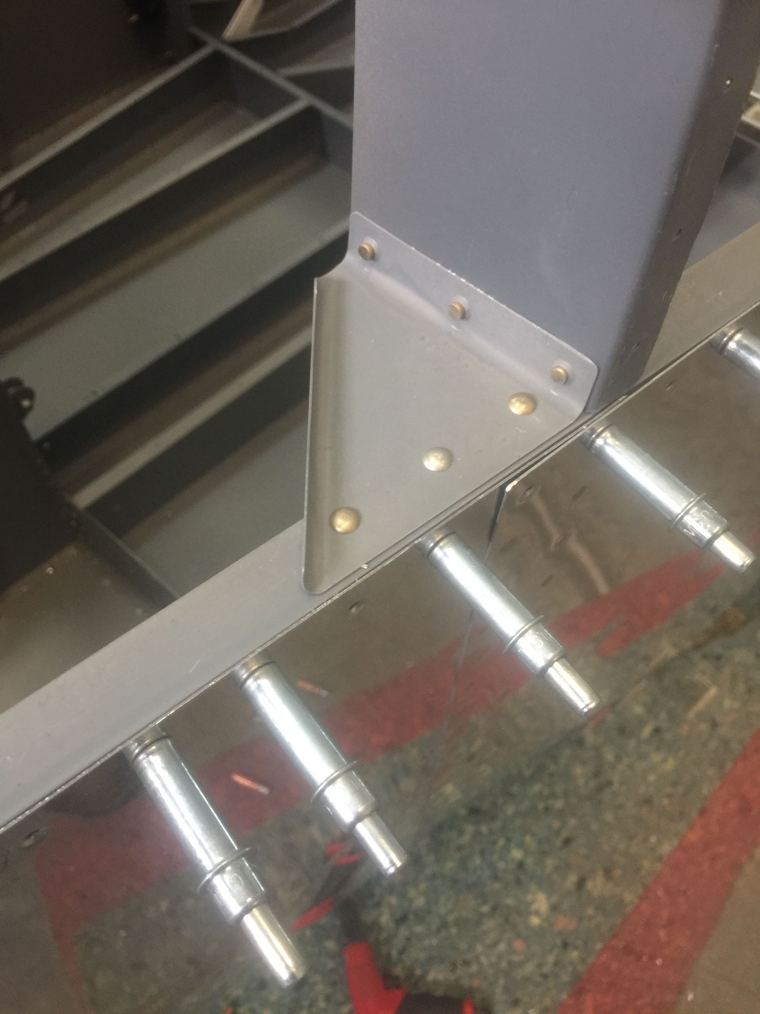
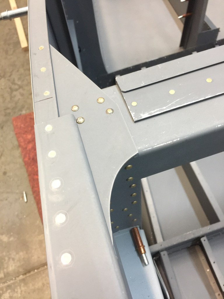
The F-695 gussets attach the main longerons to the angle frame of the firewall. I drilled the holes in the gussets, then clamped the gussets to the longeron and horizontal angle of the firewall. I then drilled the gusset to the firewall and the longeron. After final preparations, I riveted the gussets to the fuselage.
Time: 4 hours
Referring to DWG 25 I noticed that the F-721B side rails had already been drilled to the longerons. I trimmed the F-757 gussets to the shape required by my canopy and tried them for fit by sliding them into the slot in F-721B. I filed and radiused the outside edge until the pre-punched holes in the F-757 matched the holes in the F-705 bulkhead.
Removing as little metal as possible I drilled and clecoed the pre-punched holes to fix the F-757 in position, then drilled the holes through the longeron and the outboard portion of F-757. Then I riveted both side rails, canopy decks and gussets to the longerons and carefully filed the decks and rails to fit the contour of the side skin.
Time: 8 hours.
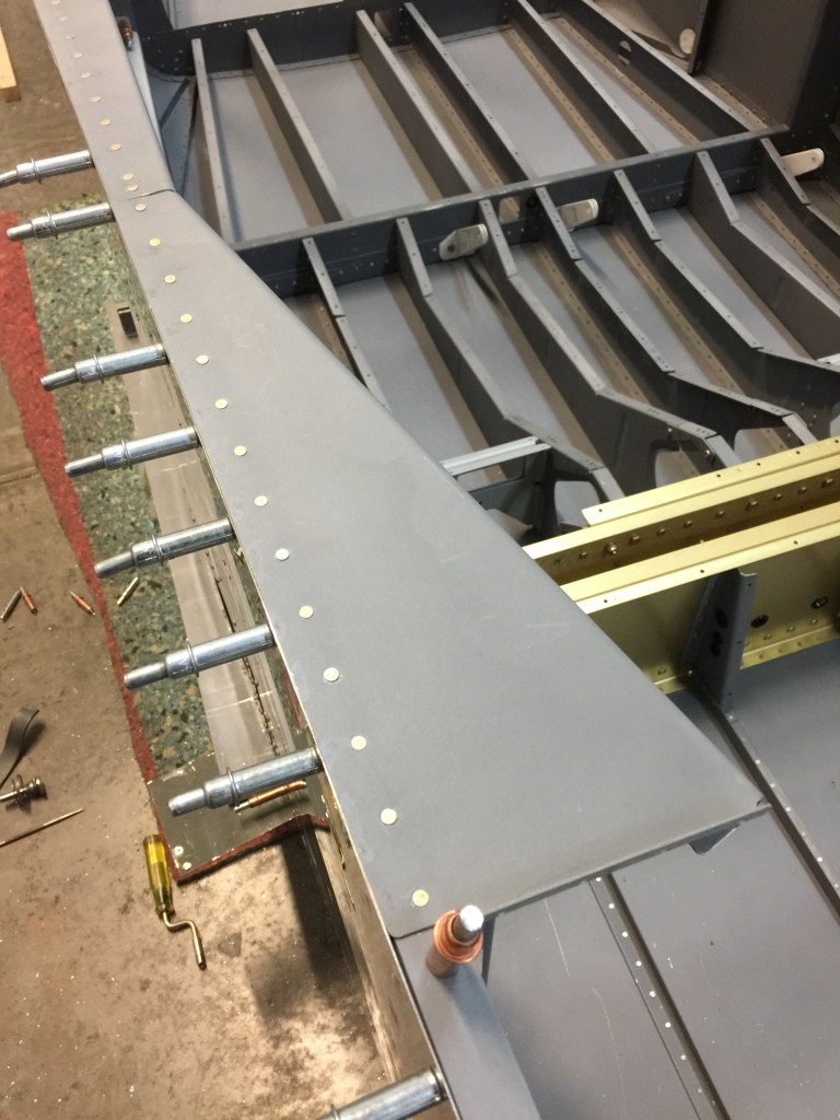
After the all the skins were riveted on, I rolled the fuselage right side up and set it at a convenient working height on a pair of sawhorses. Then I leveled the fuselage at the center section, both lengthwise, along the longerons, and sideways, across the longerons and secured the fuselage so that it stayed that way.

Referring to DWG 26 I clamped the F-714 aft deck to the longerons, using clamps through the forward lightening holes and rear rectangular opening. I placed a level across the rear deck, near F-710. I loosened the clamps and twisted the fuselage slightly until it read level.

I took my time with this step as once the aft deck is riveted to the longerons, the fuselage is torsionally rigid, and any twist built into it would be there forever.

When the fuselage was straight, I re-clamped the aft deck and drilled it to the longerons.
After deburring and priming I riveted the aft deck to the fuselage.

Time: 4 hours.
Before the F-770 forward side skins could be riveted to the fuselage framework, there was a laundry list of small tasks that had to be completed.
First I completed the necessary dimpling or countersinking on the F-770 skin and underlying structure.
Then I removed the F-796B and clecoed the F-796C & D spacers to the F-796B angle. I aligned part edges and match-drilled all the holes through F-796C & D using the holes in F-796B as guides.
The skin was removed and the F-684 Gussets were riveted to the vertical firewall angles as shown on DWG 23, Detail A. I riveted the F-7101 Gear Attach Web to the F-902 bulkhead (DWG 23, Sect G-G’.)
I then riveted the F-719 and F-719B Stiffener and Angle Clip to the vertical angle of the firewall.
I clecoed the angle and spacers back in the fuselage and removed the parts and set them aside for later installation.
I ‘pre-riveted’ the F-704H Center Section Side Plate (DWG 11) to the F-770 skin. A few key rivets were set at this time, because they would have been very difficult to reach when the skin was installed on the fuselage. These rivets were right next to the spar entry cut-out. I set the upper five rivets forward of the spar cut-out, and left the lowest one open … it was riveted later when the skin went on. I then set the six rivets aft of the spar cut-out.
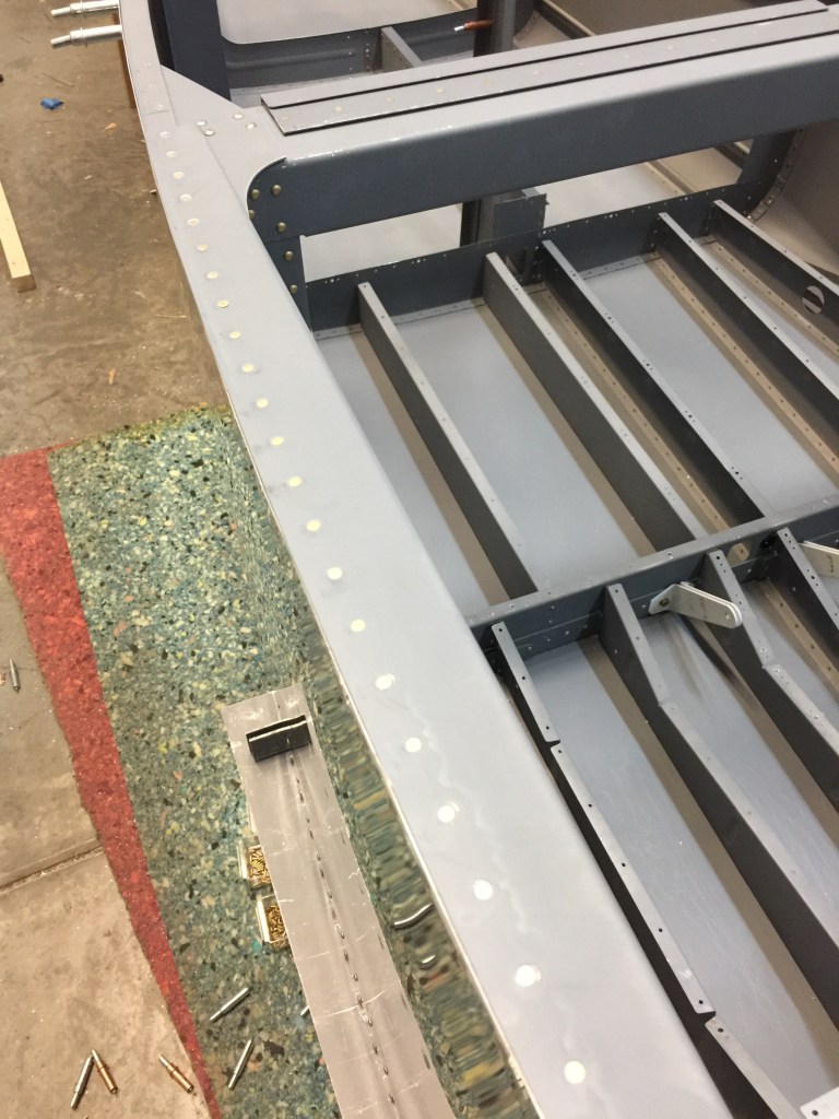
When the preparations were complete, I riveted the F-770 side skins to the fuselage, starting at the F-704 bulkhead and working fore and aft. I then finished riveting the F-772 skins.

I completed riveting on the aft fuselage that had not been finished yet. I remembered to rivet the skins to the main longerons with only the rivets specified. The rest of the holes needed to be left open to attach the top skins.
Time: 8 hours.
I assembled the brakes to the rudder pedals.
The outboard five rivets holding the F-772 and F-776 Bottom Skins to the F-704A Forward Bulkhead had to be installed “double-flush” as shown in drawing 28. The flush heads resting on the inside of the F- 704 flange are necessary to provide clearance for the RV-7A main gear leg mounts that would be bolted into this location.
I next assembled the F-6117-L&R Brake Pedals. The Wd-655R&L Rudder Pedal Assemblies were assembled with the brake and master cylinders bolted on as shown on the Exploded View of DWG 37. The F-6116 Side Bearing Blocks were slipped over the end of the rudder pedal tubes and the assemblies were dropped into the fuselage from above. The right side pedal assembly is forward of the left side.
The exact fore-and-aft location of the F-6116 bearing blocks was left to the builder. I drilled three sets of hole patterns so the location could be changed easily if it becomes necessary. I remembered to maintain at least two hole diameters between the edges of the holes.


Time: 2 hours.
