Installing the Auxiliar Longerons and Forward Bulkheads – 3

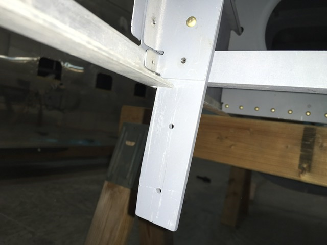
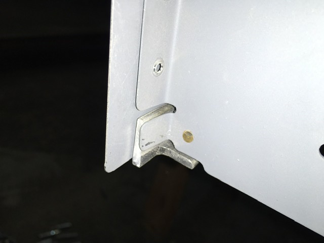
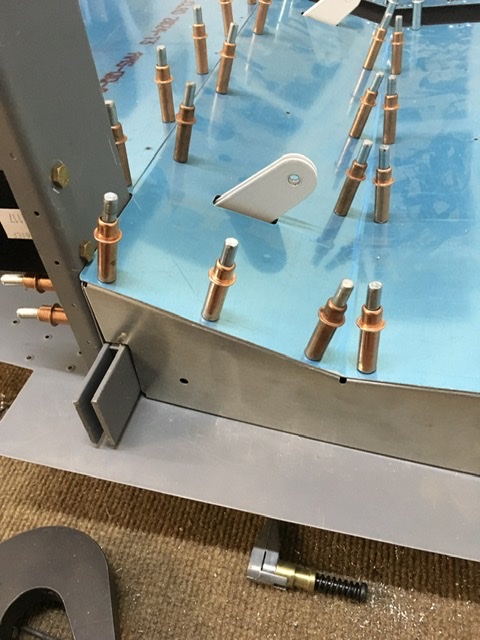
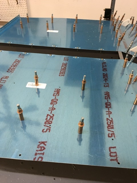
I made the F-717-R&L Lower Longerons which were simply lengths of AA6-125 x 1 x 1¼ angle. The aft end was cut at an angle to butt against the vertical side of F-704, and 4 1/8” of one leg of the angle was removed as shown on the plans. This was for clearance of the F-7114 gusset (RV-7) or the WD-721 landing gear mount (RV-7A) as  seen on DWG 34 or 34A. To mate with the curving forward fuselage, this longeron had to have a bit of twist.  I clamped the longeron in a sturdy vise with the forward 3-7/8″ captured between the jaws and used a large padded crescent wrench on the vertical leg of the angle to twist it outboard. I worked in small steps and fit the longeron to the fuselage until it “nested” well with the Wd-603 bracket (see Section K-K’) and butted against the forward edge of the F-704 bulkhead (see Section N-N’.)  The vertex of the longeron needed to parallel the lower edge of the F-770 side skin. About 1/8” of the longeron was visible, extending below the edge of the skin. When the longeron fit in Wd-603, I clamped the assembly and drilled the four vertical bolts shown in Detail L, Detail A and the Side View of DWG 23. I clamped the aft end of the longeron to the F-704 bulkhead for the time being.

Time: 3 hours.

Installing the Auxiliar Longerons and Forward Bulkheads

I started by drawing lengthwise centerlines on Auxiliary Longerons F-713-R&L. I then trial fit the longerons between the firewall brackets and the F-704 bulkhead. To fit properly, the longeron had to be twisted slightly and the aft end had to be filed at an angle to butt against the F-704. I clamped the forward end of the F-713 and wiggled the aft end until the centerline appeared in the pre-punched holes in the F-770 side skin.  I then drilled and clecoed the assembly.

E19C6CA6-14F1-42C8-8479-7E183E026A23132780DB-CD67-491C-B161-5986B3BDA5B89057FDFE-BDB6-4ED4-9C2F-CD45C3EF8450FF5E2FC6-429C-4B29-AB55-6CF2F85CBFBA

Time: 2 hours.

Adding the Forward Fuselage – 2

I made the four F-704-L straps shown in Detail D, DWG 23.

Then I removed the forward six or seven clecos from the longerons and set the firewall in place. The rear facing “fingers” of the WD-602 brackets rested on the inside of the longeron angles. I clamped the firewall to the longeron.

I then drew a centerline on the flange of the aluminum firewall angle. I clecoed the F-772 Forward Bottom Skin to the F-704 bulkhead. Then I clamped the skin to the firewall with the line centered in the 2nd row from the front edge. Then I drilled a hole on each side of the fuselage, through the skin and angle. This set the distance between the firewall and the F-704 bulkhead.

I slipped some AN470AD4 rivets into all the holes in the skin and longeron between the firewall and the aft end of the WD-602. At this point, these holes had not been drilled through the steel brackets and the firewall was heavy enough to cause some sag in the longerons and make the holes mis-align.

I took a short break for a few minutes and returned to recheck that:

1. The forward face of the firewall was 5/8″ aft of the forward edge of the F-770 skin.

2. The webs of the longeron angles were clamped tightly to the Wd-602 brackets.

3. The 1/8″ holes in the F-770 skin and longerons were still aligned -in other words, 1/8” rivets slipped easily into the holes.

When all these things had come to pass, I drilled the F-770 skin to the flanges of the firewall, starting at the top longeron and working toward the bottom.

Adding another couple clamps to the longeron/bracket assembly I continued the holes already in the longeron and skin through the steel brackets and put a cleco in each hole as I drilled it.

Time: 4 hours.

Adding the Forward Fuselage

At F-704, I clamped the longerons even with the upper edge of the F-770 skin. I then checked the forward edge of the F770 to be sure that the skins extended 3/4″ past the forward edge of the longerons.  I needed to trim the longerons slightly with a cutting disc in the grinder to obtain the minimum of 3/4”.

F374A25B-085D-4361-9D1D-91AF7065480994619BED-B784-47C5-B5BF-2F142E5D2F77

I then drilled the remaining holes connecting the longerons to the F-770 skin.

Time: 3 hours.

Joining the Rear and Center Fuselage Assemblies – 3

At this point all the skins below the main longerons and aft of F-704 were clecoed to the fuselage skeleton. I clamped the skins aft of F-704 to the longerons, making sure that the corner of the longeron was flush with the edge of the skins.  I began drilling all the holes through the skins and the longerons, starting at the tail and working forward.  I noted that on the F-773 side skins that there was a “rivet between rivets” several places along the main longerons. These rivets had been used to fasten the skin and longeron during construction. The rest of the holes were left open to be used when the top fuselage skins are installed.
69CEB2AC-B8C2-4EB2-8A9E-EC0099CEF2BBAF2A4C89-8FDC-4641-99C8-AEA24839D79E6D7BE0A8-B29A-47B8-92F4-9FB6D216C097


Time: 3 hours.

Joining the Rear and Center Fuselage Assemblies – 2

The F-770 forward side skins were fitted next.
EAD0037B-037C-4BCE-AF37-26584D5782EBECDA8D35-0025-482E-97DF-7113392336D33CDCC776-3FCE-4EFC-8BF6-472679C6C38B

I was installing the optional step on each side of the fuselage, so I used a hole saw to drill the F-770 where the tube of the step would pass through, using the pilot holes to show the location.

I then clecoed the F-770 forward side skins to the F-704, F-705, and F706 bulkheads, and the F-773 aft side skins.  It was necessary to raise or lower the tailcone slightly to align the holes.

I used a straight edge to mark the flanges of the F-623 corner ribs where the step comes through using the F-770 forward side skin and F-725 baggage rib as a guide. I then removed the ribs and trimmed them on the table.

Then the forward ends of the main longerons were checked to see that they followed the top edge of the F-770 side skin.  The bend/twist in the longeron was adjusted until they did.

I fit and drilled the F-720 armrests, fluting them lightly between the holes in the armrest to make them match the holes in the fuselage side skin.  After drilling, I removed and stored the armrests as they would be installed after the side skins are riveted on and the seat floors are installed.

The LP4-3 blind rivets would also be installed later, after the installation of the F-704Ks.

13BC5AF5-492D-4A6E-9BA0-EFABC70101FB4DE2364A-571F-4EFF-B96B-9426E3974186

I removed the F-770 forward side skins to make the conical bend at its lower aft end which would be rolled to fit the aft fuselage. I clamped the F-770 to the table with a couple of C-clamps and a length of angle and arranged the skin so that the bend line rested between the edge of the angle and the edge of the table. I drilled a piece of scrap AA6-125 angle to match the lower edge of the skin and clecoed it to the skin, using clecoes in every hole.   The bend of the skin was very tight -a sharp 90 bend – on the forward end, and opening to a gentle curve at the aft end.  I clampEd visegrips to the aft end of the angle and used a twisting, rolling motion to start the curve. At the same time, I used a strong push with the thumb of the other hand to form the tight bend at the forward end. It took several tries and trial fits to form a bend that made a smooth transition to the rear fuselage.

5B8112DC-8831-47FE-BBCD-9C5D1C65494F0688B998-32AC-4E15-A037-EBA3A2A1BD89

I also made and installed the F-623A Rib Attach Strips that fastened F-623 to F-705, as illustrated by View C-C’, DWG 22.

Finally I clecoed the F-770 skins back on the fuselage.

Time: 8 hours.

Joining the Rear and Center Fuselage Assemblies

It was time to join the aft and center sections of the fuselage. I placed the tailcone assembly upside down on a couple of sawhorses and added another sawhorse on the forward side of the tailcone assembly approximately where the F-704 bulkhead would rest. I set the F-718 longeron assemblies on either side of the aft fuselage and removed just enough clecoes from the F-773 side skins to allow the longeron to be slipped into the notches in the bulkheads. I aligned the vertical leg of the aft end of the longeron with the aft end of the flange of F-712. I then notched the longerons to fit around the F-711C bars as shown on DWG 18.

2F5716DC-8608-4BF0-BEB6-42424D5FAFEAF8FEA28D-BD5D-4429-BAC6-6565687F1CC3A44044F5-E97B-4D4F-8C37-7EFA2660ED910836D387-874A-4F13-AFB1-D2F0CE7EB58D33304BF8-8DCA-4339-A921-799DAAF1A93F94030FE2-2C0E-4A2B-84FF-E28CBBEE7DE5

I was careful to notch the longerons, not the F-711C bars! With the longerons in place I re-clecoed the side skins to the bulkheads. I added a few clamps to keep the longerons aligned with the top of the side skin.

I then placed the center fuselage in position. I placed the top of the F-704Cs so they rested on the third sawhorse. I slipped the F725, 726, and 727 baggage ribs and the F-776 center bottom skin into place over the F-706 bulkhead and F-778 aft bottom skin. I then clecoed the F-725, 726, and 727 baggage ribs to the F-706 bulkhead from the rear and clecoed the F-776 center bottom skin to the F-706 and the F-778 aft bottom skin.

Time: 5 hours.

Assembling the Center Fuselage – 4

I drilled the F-715 outer seat rib to the F-704 bulkhead. I also drilled it to the F-776 centering the centerline on the bottom flange in the holes in the bottom skin. I positioned the top of the rib so the distance between the outside of the web and the outer edge of the seat skin was 0.032” using a bit of scrap for a spacer. This meant that a thin strip of flange was visible past the edge of the seat skin when viewed from the top. I left the seat and baggage skins clecoed in place to help keep the fuselage stiff and straight during the assembly.

68A1C6D9-965B-43BC-9225-94D19C34D88A6C6CA820-F967-48F2-8BFA-AD3A9A17CE9C


Time: 3 hours.