
With the main spar bolted in place, the next step was the attachment of the rear spars. I leveled the fuselage, both laterally and longitudinally, using the top surface of the F-718 longerons between F-704 and F-705 as a datum surface. I then squared the wing with the fuselage. This was done by measuring from corresponding points on the wing tips to a common centerline point of the aft fuselage.


I equated these distances at the same time checking that the wings had no forward or aft sweep. This was done by dropping 4 plumb lines from the wing leading edges (2 on each wing at inboard and outboard points) to see that they all fell in a straight line. I marked this position with a vertical line at the rear spar attach, on both rear spar and center section.

Now the very important incidence angle had to be measured and set. This was done by using a level and spacer blocks as shown in DWG 38. I verified that the fuselage was level and rested one end of a level on the forward spar just forward of the skin butt joint and the other end on a spacer placed directly over the rear spar web. I shifted the rear of the wing up or down to center the level. The spacer size was calculated to provide the desired 1 degree positive incidence angle. I checked several points along the span of the wing to verify the reading. I clamped the root in place and checked the other side in the same manner. See DWG 38, Section H-H.

It is extremely important to verify that there was at least 5/8” from fastener center to the edge of the part, in both the rear spar and F-705.
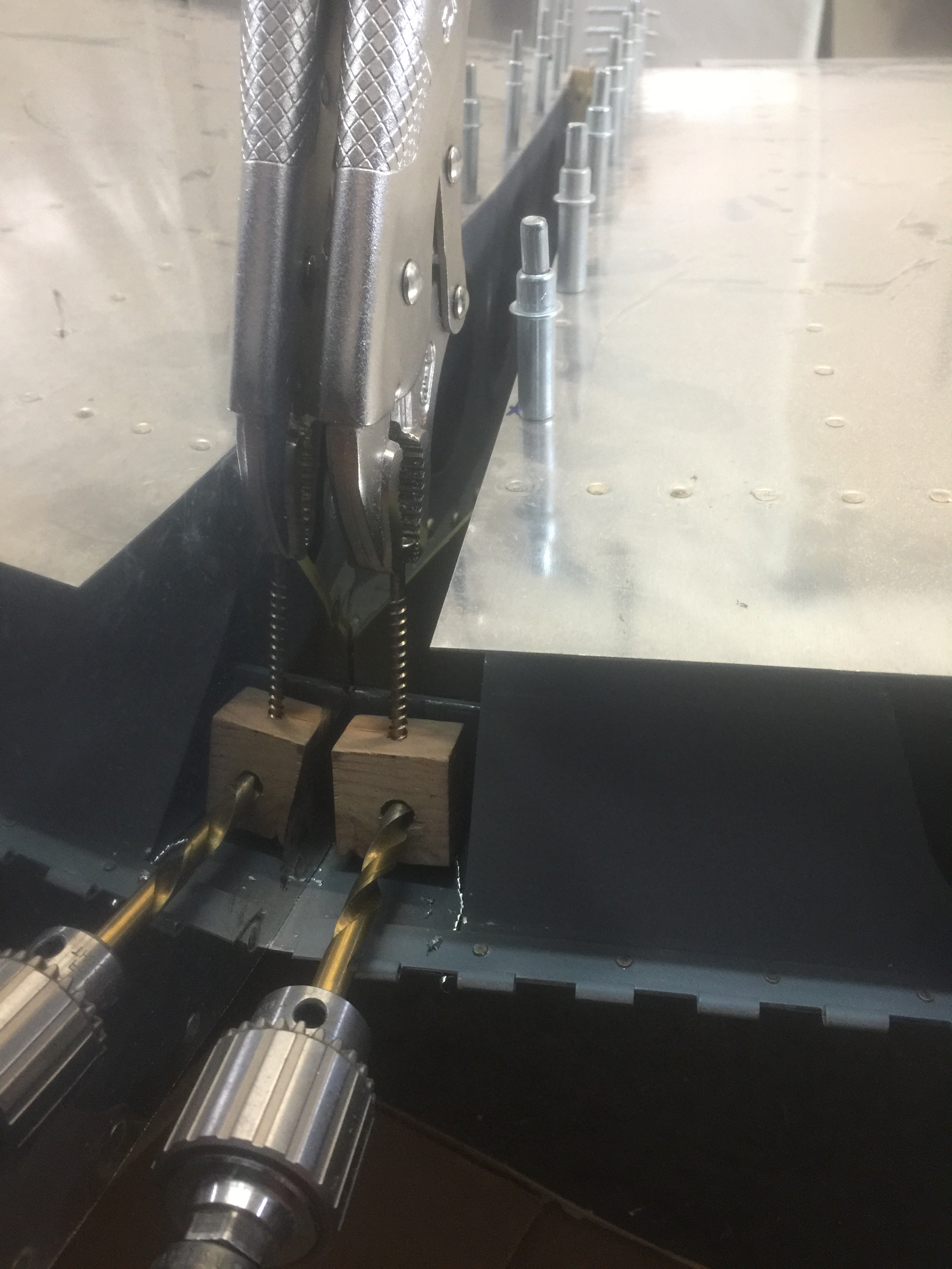
I initially drilled an undersize hole starting with a 1/4” drill. Then I progressively enlarged the hole to 5/16” to provide a close fit for an AN5 bolt. Drilling with a long stiff drill bit was a good idea because it could be held straighter for a truer hole.
The overlapping portions of the F-776 bottom skin were to be screwed to the bottom of the wing when the wings would be installed to stay. Holes for these screws had be drilled now. I used the reference lines to locate the hole positions. After the wing was removed, these holes were dimpled for #8 screws. K1100-08 platenuts were riveted to the inside flange of the root rib.
The F-796A Fuel Tank Attach Brackets were fitted to the fuselage as shown on DWG 38, Detail F. The bracket needed to have the main web adjusted by bending so that it mates flush to the fuselage side and to the T-405 angle bracket on the fuel tank, as shown on DWG 38, Section E-E. I clamped the F-796A angle firmly to the T-405 bracket on the fuel tank. I checked to see that it rested firmly against the fuselage and then drilled the attach holes.
Time: 6 hours.
