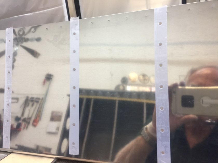
The construction technique for RV-7/7A ailerons is similar to that of the elevators. The aileron uses ribs at the ends only; light angle stiffeners support the rest of the skin. The skin stiffeners are provided with the rivet holes pre-punched but not cut to length. The aileron skin is punched to match. These are match-drilled much like the stiffeners in the empennage. I cut and trimmed the stiffeners as indicated. I then located the stiffeners on the inside of the rear aileron skin and match drilled.
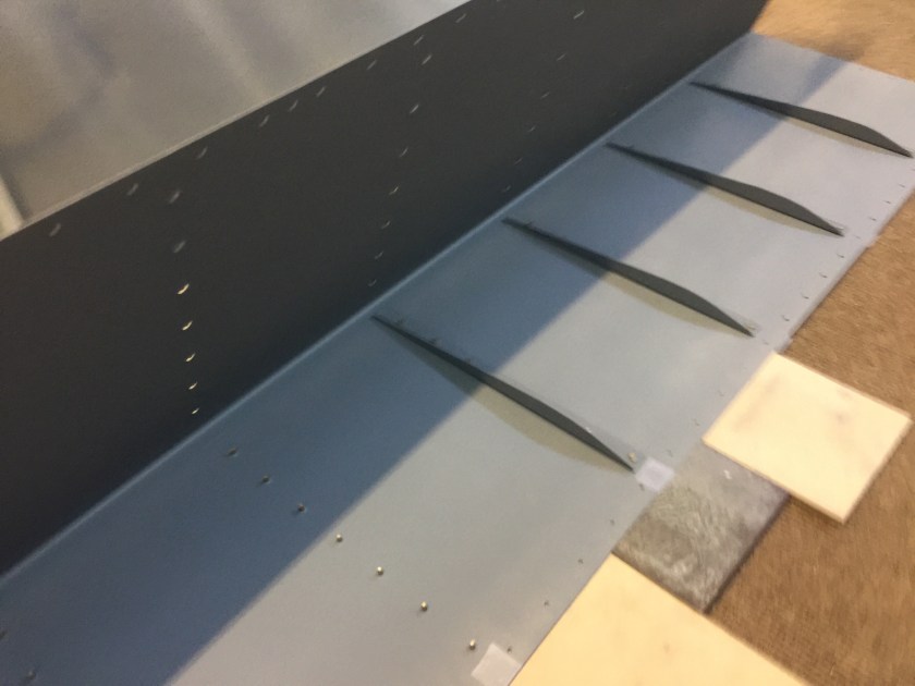
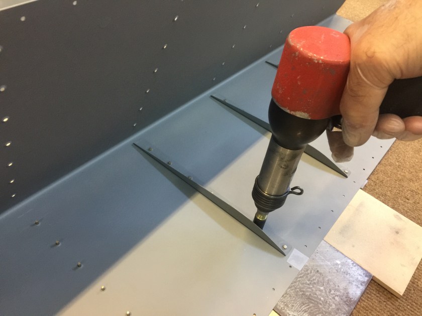
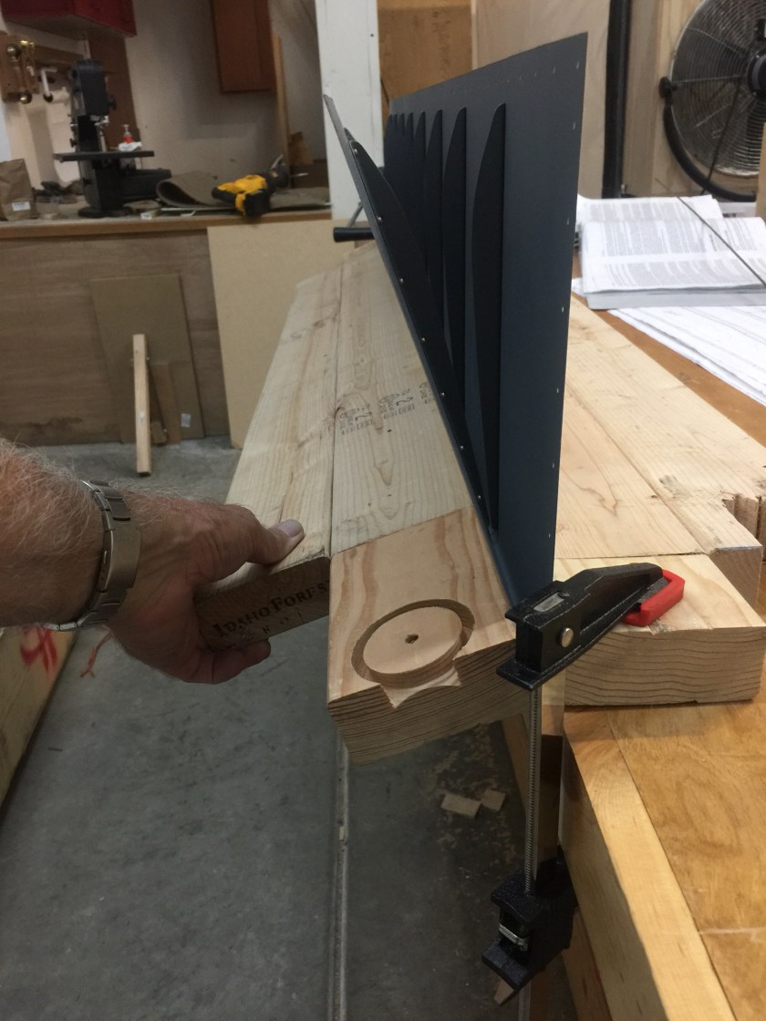
I dimpled the stiffener angles and skin. After priming, I riveted the stiffeners onto the skin, using the backriveting method. Following this, I completed the trailing edge bend using the homemade bending brake used on the empennage. The bent skins needed to be straight up to the radius and the radius had to be between 3/32” to 1/8”. I matched the degree of bend to the full size end view drawings. The upper and lower skin just touched the spar when placed in position.
The aileron spar is not symmetrical; the top and bottom flanges are bent to different angles. I checked and labeled each spar for top, bottom, inboard and outboard. I made aileron spar reinforcement brackets from supplied .040” material. Then I match-drilled using spar holes as a guide and clecoed as I went. I clecoed the aileron brackets in place and drill #12 for the attach bolts. I labeled the parts, disassembled , deburred & primed. Making sure that I left the holes that would later attach the ribs empty, I riveted the aileron spar reinforcement brackets on the spar along with the plate nut.
The wide tabs on the top of the nose ribs had no pre-punched holes, they would be match drilled from the nose skin. I fluted the center of the tab slightly to remove distortions from the manufacturing process and used the nose skin holes as a check for straightness. I then clecoed and match drilled the nose ribs to the spar.
I looked closely to be sure that had installed the aileron ribs correctly as they were not symmetrical. The tooling holes were nearer the bottom of the aileron. I clecoed and match drilled the main ribs to the spar.
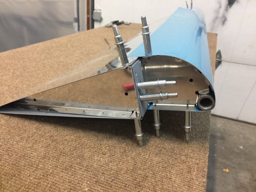
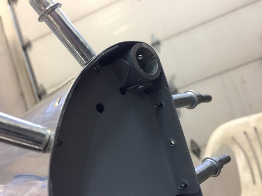
I clecoed the leading edge skin and the trailing edge skin to the spar with the counterbalance pipe in place. I match drilled the skins to the skeleton including the #30 holes in the counterbalance pipe. The holes along the bottom of the spar were opened to #30 for the blind rivets. I then removed the trailing edge portion and re-clecoed the leading edge in place with the counterbalance pipe in position. Using a long 1/8” drill, I went through the lower hole that attaches the nose rib to the spar and drilled through the tab on the rib into the counterbalance pipe.
I disassembled the parts, deburred, dimpled and primed. I machine countersank the holes in the counterbalance pipe.

Attach the nose ribs to the counterbalance with blind rivets. Bend the tab on the nose rib just enough to clear the rivet tool.
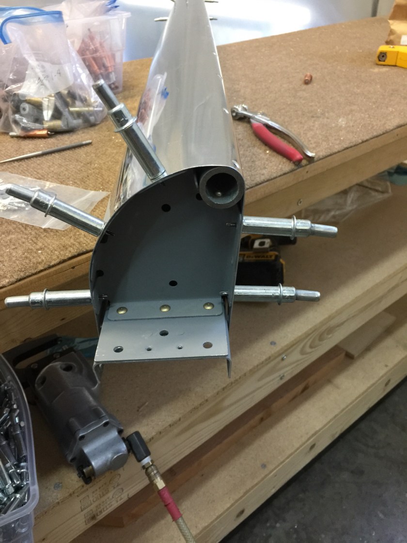
I clecoed the leading edge skin to the counterbalance/rib assembly and rivet the nose ribs to the spar. Then I clecoed the aft skin to the spar. Leaving out the main ribs and the clecos along the bottom of the spar to allow access to the inside I riveted the leading edge skin and trailing edge skin to the top of the spar. Then I riveted the nose ribs to the the top half of the nose skin only, inserted the main ribs and riveted them to the spar and top of the aft skin. Then I installed the aileron brackets.
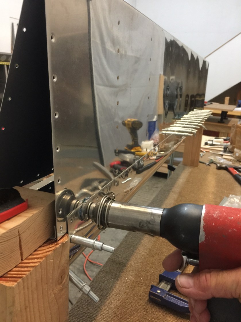
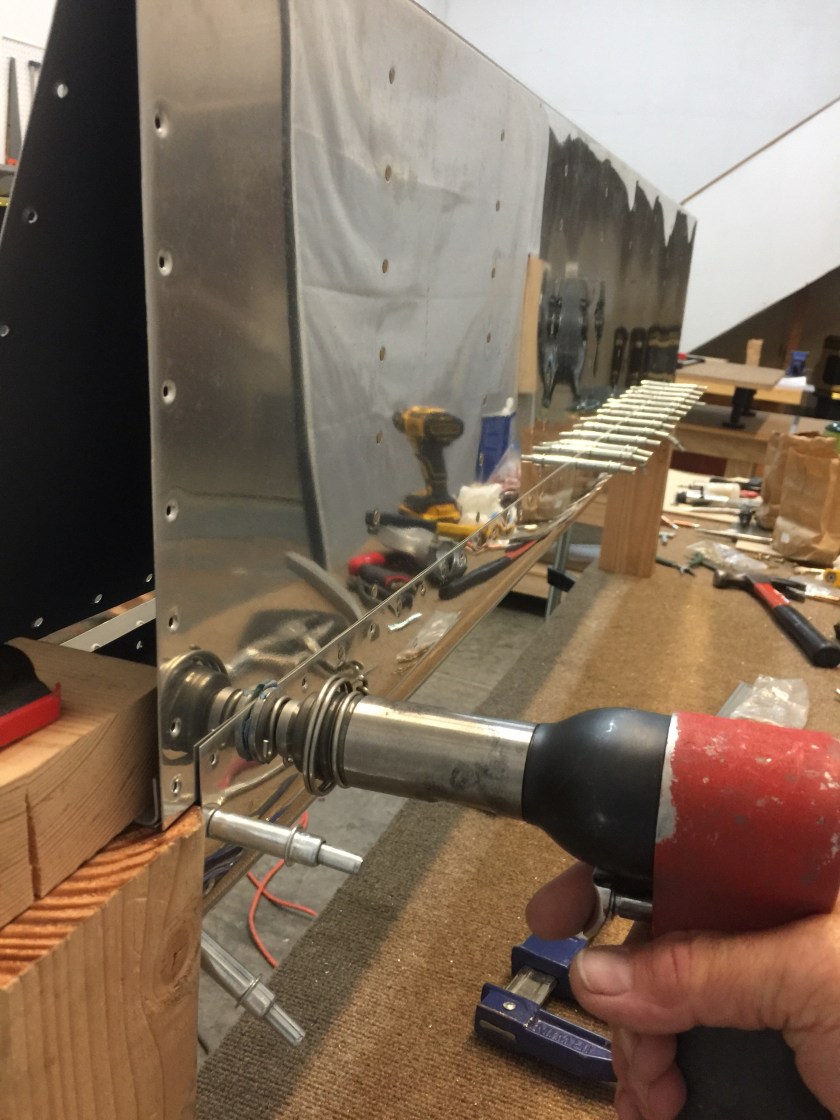
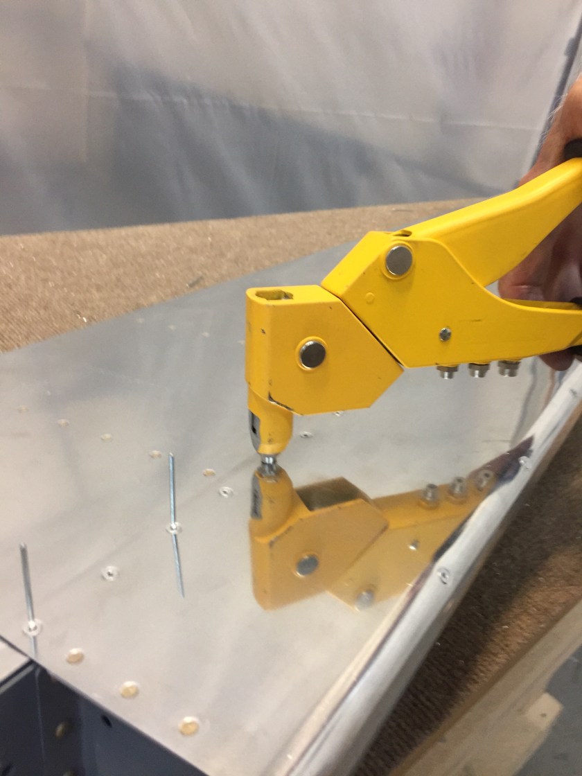
I flipped the assembly over , clecoed it together and weighted it down on the flat work surface. I blind riveted the counterbalance pipe to the leading edge skin. Checking that the aileron was flat, I riveted the bottom side of the nose rib to the skin. I then riveted the bottom side of the main ribs to the aft skin. Lastly, I blind riveted the leading edge and aft skins to the spar.
Time: 8 hours.
